
More project photos (2)
The problem
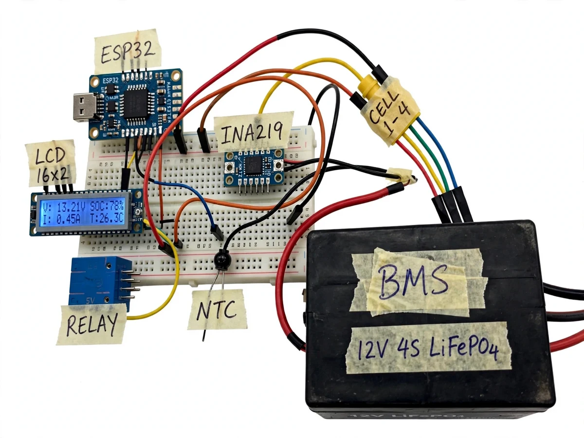
Lead-acid and lithium battery packs in solar installations, e-rickshaws and UPS systems die early when nobody watches their health: a single weak cell drags the whole 4S string down, over-discharge sulfates the pack, and the owner discovers the damage only when the load dies. A proper battery monitor turns the invisible visible — current in and out, per-cell voltage spread, temperature and cumulative cycle count — so the user can act before a cell is destroyed. This project builds that monitor as a working prototype: an ESP32 with an INA219 current sensor sits in series with a 12V 100Ah LiFePO4 pack, balance taps report each cell's voltage, an NTC watches temperature, and the firmware integrates current over time (coulomb counting) to report state-of-charge, corrected at rest by the LiFePO4 open-circuit voltage curve. A relay provides an armed over-temperature cutoff. All of it is visible on a local web dashboard and a 16×2 LCD, making the sensing chain — sensor, calibration, algorithm, display — completely demonstrable.
How it works
- The INA219 is wired in series with the pack on the high side; balance taps from the 4S string are divided to ADC-safe levels for per-cell voltage.
- The ESP32 samples bus voltage and current (typically 1 Hz), computes pack voltage and applies a two-point calibration from the buyer's own measurement procedure.
- Current samples are integrated over time to track charge in/out; when the pack rests, SoC snaps to the LiFePO4 open-circuit-voltage lookup table.
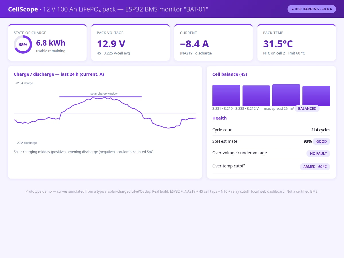
- Each cell voltage is compared against the group mean; a spread above the warning threshold flags the cell on the dashboard and LCD.
- Cycle counting accumulates full-equivalent cycles; SoH is estimated as remaining usable capacity versus the 100 Ah design rating.
- The NTC thermistor reading drives the over-temperature logic — crossing 60 °C de-energises the relay output and latches a FAULT state until reset.
- All readings are served on the ESP32-hosted CellScope dashboard over Wi-Fi and mirrored to the 16×2 LCD.
Tech stack:
- ESP32 (Arduino framework)
- INA219 current sensor · NTC thermistor
- 4S balance taps with resistor dividers
- 5V relay module (over-temperature cutoff)
- 16×2 LCD (I2C)
- HTML/CSS/JavaScript local web dashboard
- Coulomb counting + OCV recalibration algorithm
- 12V 100Ah LiFePO4 4S pack (demonstration unit)
| Parameter | Value |
|---|---|
| Pack | 12V 100Ah LiFePO4, 4S (demonstration unit) |
| Current sensing | INA219, ±3.2 A range, 0.1 mA resolution (datasheet) |
| Cell voltage taps | 4S, ADC-divided, approximately ±10 mV after calibration (expected) |
| SoC method | Coulomb counting with OCV rest recalibration (design logic) |
| SoC accuracy | Typically ±3–5% after buyer calibration (design target, not measured) |
| Temperature | NTC thermistor, cutoff at 60 °C (configurable) |
| Cutoff output | Relay, 10 A contacts (design scope) |
| Dashboard | ESP32-hosted local web page + 16×2 LCD |
| Sample rate | Approximately 1 Hz (design scope) |
| Supply | Pack-powered via buck converter (design scope) |
Project features
- [Coulomb-counted SoC] The firmware integrates INA219 current over time for state-of-charge, recalibrated against the LiFePO4 open-circuit voltage curve whenever the pack rests.
- [4S cell-balance view] Individual cell voltages from balance taps are shown with the max spread in millivolts, so an unbalanced cell is visible before it causes damage.
- [INA219 current sensing] High-side bidirectional sensing measures both charge and discharge current with the sensor's ±3.2 A / 0.1 mA resolution range (datasheet).
- [State-of-health estimate] Cycle count plus capacity-fade tracking against the pack's 100 Ah rating yields an SoH percentage graded GOOD / DEGRADED.
- [Over-temperature cutoff] An NTC on cell 2 feeds a comparator-driven relay output that disconnects the load at a configurable temperature limit (60 °C default).
- [CellScope web dashboard] Local Wi-Fi dashboard with SoC ring, pack voltage, current, temperature, 24-hour charge/discharge chart and a cell-balance panel.
- [16×2 LCD status] Live voltage, SoC, current and temperature on the hardware itself, so the rig is demonstrable without a browser.
What is included
- Working hardware prototype (ESP32, INA219, taps, NTC, relay, LCD) with the demonstration pack
- Complete ESP32 firmware source with calibration procedure
- CellScope local web dashboard (single-file app)
- Wiring diagram and component list with part numbers
- Buyer-run current/voltage calibration procedure
- Project report PDF (coulomb counting, OCV curve, calibration, test procedure)
- PPT presentation for final review
- Viva Q&A preparation document (SoC methods, sensor accuracy, safety limits)
Limitations & prerequisites
- This is a monitor, not a certified BMS: it does not balance cells or manage charging — it observes and cuts off. The report and page state this plainly.
- SoC accuracy of ±3–5% is a design target after the buyer's own calibration run; no figure is claimed as measured before that run.
- The demonstration pack is a 12V 100Ah unit; adapting the divider ratios and current range to other pack sizes needs the documented rescaling steps.
- Coulomb counting drifts between rests; long continuous cycling without rest periods reduces accuracy, documented as a limitation.
- The relay cutoff is a prototype-grade disconnect, not a safety-rated contactor for high-current traction use.
- Wi-Fi dashboard is local-network only; no cloud logging in the base build (logged to serial / future scope).
Frequently Asked Questions
How is state-of-charge actually calculated?
By coulomb counting: the firmware integrates the INA219 current readings over time to track amp-hours in and out. Because integration drifts, the SoC is corrected against the LiFePO4 open-circuit-voltage curve whenever the pack rests — the two methods together are the standard approach for this chemistry.
Why does the cell-balance view matter?
In a 4S pack the weakest cell sets the limit: charging stops when the highest cell hits the limit and discharging stops at the lowest. Showing each cell's voltage and the max spread lets the user spot a drifting cell long before it kills the pack.
Is this a full BMS?
No — and the project says so explicitly. It is a battery monitor and protection cutoff: it measures, displays, estimates health and disconnects on over-temperature. It does not actively balance cells or regulate charging; those belong to a dedicated BMS chip, listed as future scope.
How accurate is the SoC?
The design target is ±3–5% after the buyer's calibration procedure (two-point current calibration against a multimeter, documented in the report). The abstract states this as a design target, not a measured figure, until the buyer runs their own build.
What happens on over-temperature?
The NTC reading crossing the 60 °C limit de-energises the relay output and latches a FAULT state shown on the dashboard and LCD. It stays latched until a manual reset, so the load cannot silently reconnect.
Is this project suitable for a final-year project?
Yes — for Electronics, Electrical and IoT & Embedded programs. It combines analog sensing, sensor calibration, an estimation algorithm, protection logic and a dashboard in one demonstrable rig. Suitable for B.E./B.Tech final-year projects in Electronics, Electrical and IoT & Embedded.
Components & software requirements
- ESP32 (Arduino framework)
- INA219 current sensor · NTC thermistor
- 4S balance taps with resistor dividers
- 5V relay module (over-temperature cutoff)
- 16×2 LCD (I2C)
- HTML/CSS/JavaScript local web dashboard
- Coulomb counting + OCV recalibration algorithm
- 12V 100Ah LiFePO4 4S pack (demonstration unit)
Delivery information
Built-to-order project. Delivery timeline is shared after order confirmation based on current queue.
Support terms
Complete documentation, setup guide, and viva preparation included. Support for setup and explanation provided.