
More project photos (2)
The problem
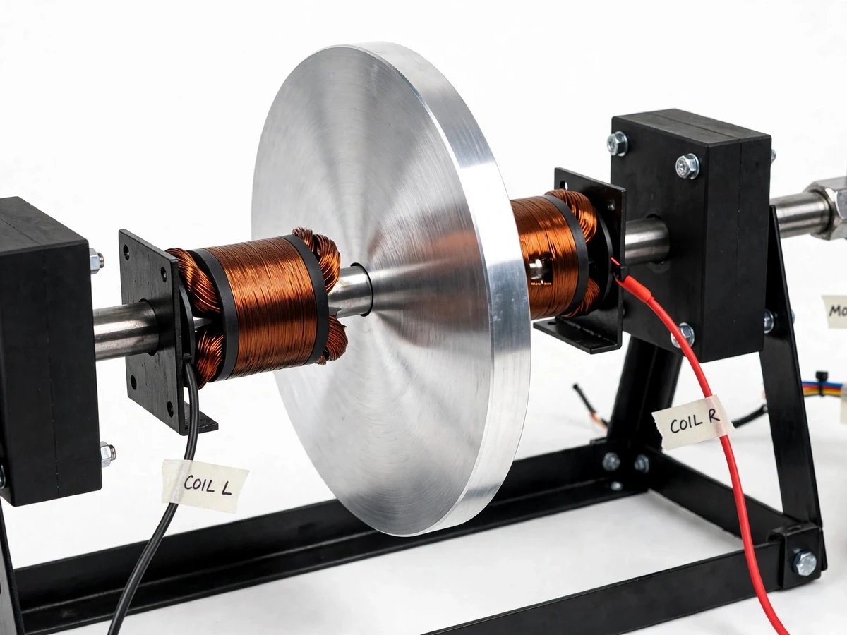
Friction brakes slow a vehicle or machine by pressing pads against a moving surface, which means wear, heat, dust and maintenance. Electromagnetic brakes avoid contact entirely: a conductive disc spins through the magnetic field of an electromagnet, and the changing flux induces eddy currents in the disc. By Lenz's law these currents create their own field opposing the motion, converting kinetic energy into heat in the disc itself. The same principle retards trains, dynamometer loads and roller-coaster runs. This project makes that principle concrete as a bench rig: a motor-driven aluminium disc passes between the pole faces of two wound electromagnets, and braking strength is controlled electrically by varying coil current. The build gives students real mechanical design (shaft, bearings, frame), real electromagnet winding work, and a genuine experimental procedure — measuring how braking time changes with excitation current — rather than a black-box demo.
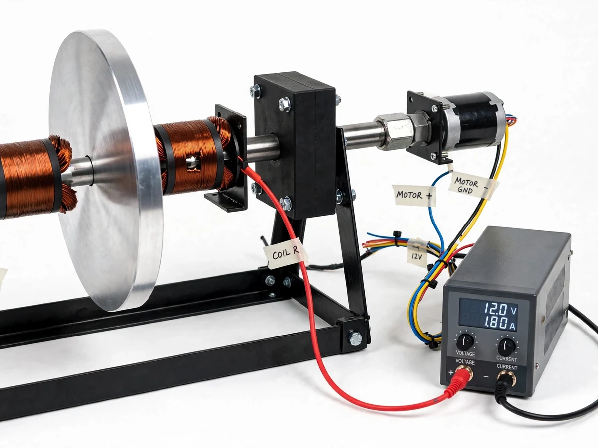
Spins the aluminium disc through the flexible coupling at the supply-set speed.
Follow the working sequence
How it works
- The 12 V DC motor spins the aluminium disc through the flexible coupling at the supply-set speed.
- With the coils unpowered, the disc runs freely (apart from bearing friction) — this gives the baseline run-down reading.
- DC current is applied to the two electromagnet coils, producing magnetic fields through the disc from both faces.
- As the conductive disc cuts the flux, eddy currents are induced in it; their magnetic field opposes the change that created it (Lenz's law).
- The opposing field produces a braking torque proportional to disc speed and to the square of the flux density — braking is strong at high speed and weakens as the disc slows.
- The tachometer records rpm decay over time; repeating at higher coil currents shows stronger braking.
- Once the disc nearly stops, the mechanical parking brake engages the disc edge and holds it at rest, since eddy torque cannot.
Tech stack:
- Electromagnet design (C-core + 24 SWG enamelled copper winding)
- Mild-steel shaft and pillow-block bearings
- 12 V DC motor + flexible coupling
- Adjustable DC power supply (12–24 V)
- Contact tachometer instrumentation
- MS angle-iron fabrication
- Lenz's law / electromagnetic induction theory
- Engineering drawing (frame + assembly)
| Parameter | Value |
|---|---|
| Brake disc | Aluminium, 200 mm diameter × 8 mm thick (design value) |
| Shaft | Mild steel, 12 mm diameter, on 2 pillow-block bearings |
| Electromagnet cores | Mild-steel C-cores, pole face approximately 40 mm diameter |
| Coils | Approximately 900 turns each of 24 SWG enamelled copper wire (design value) |
| Coil excitation | 12–24 V DC, up to approximately 3 A per coil (design value) |
| Air gap | Approximately 2–3 mm between each pole face and the disc (design value) |
| Drive motor | 12 V DC motor, approximately 1,000–1,500 rpm no-load (datasheet range) |
| Speed measurement | Contact tachometer (buyer-run test) |
| Frame | MS angle-iron fabrication, approximately 600 × 250 mm footprint (design value) |
| Braking torque | Not published — measured by the buyer via the supplied test procedure; speed- and current-dependent |
Project features
- [Contactless eddy-current braking] A 200 mm aluminium disc spins between the pole faces of two DC electromagnets; motion through the field induces eddy currents whose field opposes the rotation (Lenz's law), braking the disc with no friction surfaces to wear out.
- [Electrically adjustable braking strength] Coil current is set from an adjustable DC supply (12–24 V, up to approximately 3 A per coil, design value); increasing current strengthens the field and the braking torque, so braking is dialled in electrically rather than mechanically.
- [Demonstrator drive train] A 12 V DC motor drives the shaft through a flexible coupling, with the disc carried on a 12 mm steel shaft between two pillow-block bearings for a repeatable, measurable test rig.
- [Coil-current sweep test procedure] A defined buyer-run test: spin the disc to a set rpm, energize the coils at a fixed current, record the rpm decay with a tachometer, and repeat at several currents to show how braking strength varies with excitation.
- [Energy-dissipation observation] The induced currents heat the disc during prolonged braking, giving the report an honest discussion of kinetic-energy-to-heat conversion and why eddy brakes complement rather than replace friction brakes.
- [Friction parking brake] Because eddy-current torque falls to zero at zero speed, a simple mechanical friction pad engages the disc edge to hold it at rest — demonstrating the hybrid arrangement used in real practice.
- [Optional customization: encoder-based decay logging] An optical encoder with Arduino can be added on request to log rpm-vs-time curves automatically instead of hand-recording tachometer readings.
What is included
- Working electromagnetic braking rig (frame, shaft, disc, wound electromagnets, motor, wiring)
- Adjustable DC power supply for coil excitation
- Contact tachometer for the decay measurements
- Coil-winding and assembly documentation with engineering drawings
- Coil-current sweep test procedure with blank observation tables
- Project report PDF (theory, design calculations, methodology, results template)
- PPT presentation for final review
- Viva Q&A preparation document (Lenz's law, eddy currents, why no holding torque)
Limitations & prerequisites
- Eddy-current braking torque is speed-dependent and falls to zero at standstill — the rig cannot hold the disc at rest; the mechanical parking brake does that.
- No measured torque or stopping-time numbers are published; results come from the buyer's own runs using the supplied test procedure.
- Prolonged high-current braking heats the disc and coils — runs need cool-down time between trials.
- Braking strength is sensitive to the air gap; a misaligned gap changes results, and the report covers the adjustment procedure.
- This is an academic demonstration rig, not an industrial or vehicle brake — no safety or automotive claims are made.
- Disc balance matters: vibration at high rpm can skew tachometer readings.
- The coils draw up to approximately 3 A each and need the supplied DC supply — a small bench/breadboard supply cannot drive them.
Frequently Asked Questions
Is this project suitable for a final-year project?
Yes — for Mechanical and Electrical Engineering programs. It demonstrates electromagnetic induction and Lenz's law, machine design (shaft, bearings, frame), hands-on coil winding, and genuine experimental work with a tachometer-based test procedure.
What is the main principle used?
Eddy-current braking. A conductive disc rotating through a magnetic field develops circulating eddy currents; their magnetic field opposes the motion by Lenz's law, converting kinetic energy into heat in the disc with no physical contact.
Will I get measured braking-torque numbers?
No invented numbers are published. The build ships with a complete test procedure (spin to a set rpm, energize at a fixed current, record rpm decay, repeat at several currents), and the report presents the results you measure.
Why does the disc need a parking brake?
Eddy-current torque is proportional to speed, so it fades as the disc slows and is zero at standstill. The friction parking pad holds the disc at rest — this is exactly why real systems pair eddy brakes with friction brakes.
What power supply is needed?
An adjustable 12–24 V DC supply capable of approximately 3 A per coil, which is included. The coils cannot be driven from a small breadboard supply or a phone charger.
Can this project be customized?
Realistic options: encoder-based automatic rpm logging with Arduino, a copper disc variant for comparison, larger pole faces or series/parallel coil wiring, and report/PPT formatting matched to your college's template.
Components & software requirements
- Electromagnet design (C-core + 24 SWG enamelled copper winding)
- Mild-steel shaft and pillow-block bearings
- 12 V DC motor + flexible coupling
- Adjustable DC power supply (12–24 V)
- Contact tachometer instrumentation
- MS angle-iron fabrication
- Lenz's law / electromagnetic induction theory
- Engineering drawing (frame + assembly)
Delivery information
Built-to-order project. Delivery timeline is shared after order confirmation based on current queue.
Support terms
Complete documentation, setup guide, and viva preparation included. Support for setup and explanation provided.
Download free synopsis (PDF)
Enter your name and email — the synopsis PDF downloads immediately. We may send occasional project updates; no spam, unsubscribe anytime.