
More project photos (2)
The problem
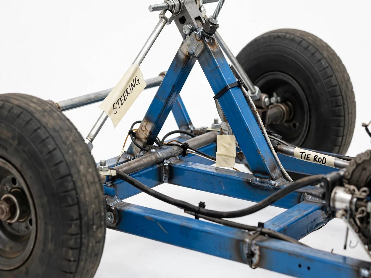
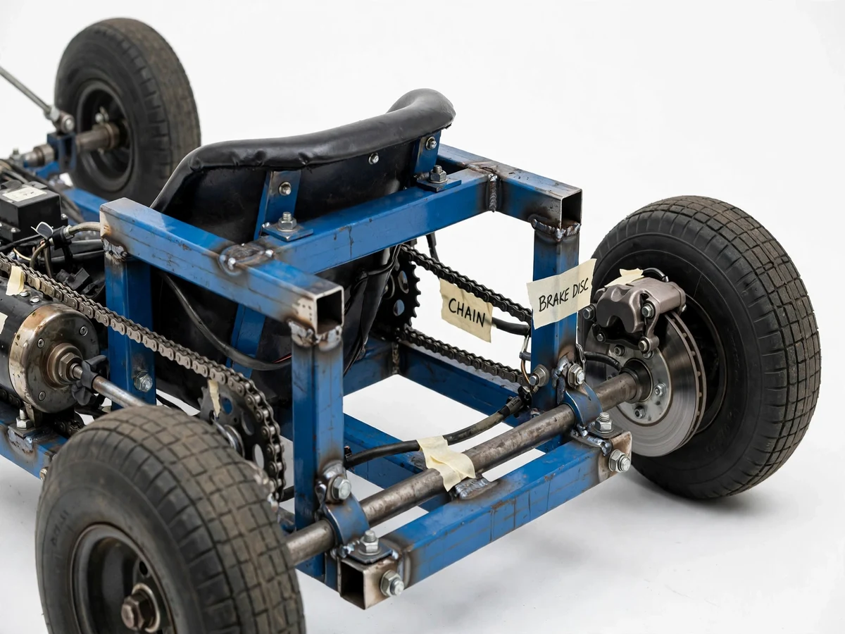
Most student go-karts are either engine-powered or built with a straight parallel steering linkage and a crude band brake on the axle. Parallel steering forces both front wheels to turn at the same angle, which scrubs the inner tyre in corners and teaches nothing about steering geometry. This project does it properly: the front axle uses a real Ackermann linkage — the steering arms are angled so the inner wheel turns sharper than the outer wheel, matching the geometry of actual cornering paths — and braking is handled by a mechanical disc brake with a steel rotor on the live rear axle instead of a friction band. The powertrain is a 48 V BLDC motor driving the rear axle through a roller chain, sized with documented gear-ratio and torque calculations. The result is a student-built kart that actually demonstrates the three systems mechanical engineers study: steering kinematics, braking mechanics and electric drivetrain design.
Twists the throttle, steers through the column and presses the brake pedal.
Follow the working sequence
How it works
- The rider twists the throttle; the hall-effect grip sends a 0–5 V signal (datasheet value) to the 48 V BLDC controller.
- The controller energises the 1000 W BLDC motor, which spins its 14-tooth sprocket and pulls the #420 chain driving the 44-tooth sprocket on the live rear axle — a 3.14:1 reduction (design target).
- The chain torque rotates the rigid rear axle, turning both rear wheels together and propelling the kart to an expected top speed of approximately 40–45 km/h (rider-weight and terrain dependent).
- Turning the steering wheel rotates the steering column; the pitman arm pushes the tie rod, which pivots both front stub axles — with Ackermann arm angles, the inner wheel steers sharper than the outer.
- Pressing the brake pedal pulls the cable that squeezes the caliper pads against the 180 mm rotor on the rear axle, converting the kart's kinetic energy into heat at the disc.
- The 48 V, 20 Ah battery pack feeds the controller, while its BMS monitors cell voltages and cuts off on overcharge, deep discharge or overcurrent (BMS protection behaviour).
Tech stack:
- MS square tube · MIG welding
- BLDC motor · 48 V controller
- Lithium-ion battery · BMS
- Roller chain · sprockets
- Disc brake · mechanical caliper
- Ackermann tie-rod linkage
- Hall-effect twist throttle
- CAD drawings · calculation file
Components & software requirements
Hardware
- MS square tube 25 × 25 × 2 mm (chassis), MS flat bar (brackets)
- BLDC motor 48 V, 1000 W with 48 V, 30 A controller
- Lithium-ion battery pack 48 V, 20 Ah with BMS + 48 V charger
- #420 roller chain, 14T motor sprocket, 44T axle sprocket
- Mechanical disc brake: 180 mm rotor + cable caliper + brake lever/pedal
- Live rear axle with 2 plummer-block bearings
- Stub axles with kingpin inclination, tie rods with rose joints, steering wheel + column
- 4 go-kart wheels with tyres, kart seat with backrest
- Hall-effect twist throttle, wiring harness, kill switch, fuse
Software / documentation - Chassis CAD drawings (2D fabrication drawings)
- Design calculation file (steering geometry, gear ratio, braking, range)
- Wiring diagram (motor–controller–battery–throttle)
- Project report PDF, PPT and viva Q&A (included deliverables)
| Parameter | Value |
|---|---|
| Chassis | 25 × 25 × 2 mm MS square tube, welded (design target) |
| Steering geometry | Ackermann linkage; inner wheel ~35°, outer ~28° at full lock (design targets) |
| Motor | 48 V, 1000 W BLDC (datasheet value) |
| Controller | 48 V, 30 A BLDC controller (datasheet value) |
| Battery | 48 V, 20 Ah lithium-ion with BMS (configurable) |
| Drive | #420 chain, 14T motor to 44T axle sprocket, 3.14:1 reduction (design target) |
| Top speed | Approximately 40–45 km/h (expected, rider-weight and terrain dependent) |
| Range | Approximately 35–45 km per charge (expected, throttle and terrain dependent) |
| Brakes | 180 mm steel disc rotor + cable caliper on rear axle (datasheet value) |
| Rider capacity | Approximately 90 kg rider (design target) |
Project features
- [Ackermann steering geometry] The front stub axles carry angled steering arms linked by a tie rod, so at full lock the inner wheel turns to approximately 35° while the outer reaches approximately 28° (design targets) — the correct Ackermann relationship that eliminates tyre scrub in corners.
- [Electric powertrain with chain drive] A 48 V, 1000 W BLDC motor (datasheet value) drives the live rear axle through a #420 roller chain with a 14-tooth motor sprocket and 44-tooth axle sprocket (design targets), sized for approximately 40–45 km/h top speed (expected).
- [Mechanical disc brake] A cable-actuated caliper clamps a 180 mm steel rotor on the rear axle (datasheet value), giving positive, fade-resistant braking that is far more consistent than the band brakes common on student karts.
- [Welded steel-tube chassis] The frame is built from 25 × 25 × 2 mm MS square tube (design target), cut, mitred and welded, with bearing hangers for the rear axle and brackets for the seat, motor and steering column.
- [Hall-effect twist throttle] A twist-grip throttle feeds a hall sensor signal to the 48 V, 30 A BLDC controller (datasheet value) for smooth, proportional speed control from standstill.
- [Battery pack with BMS] A 48 V, 20 Ah lithium-ion pack with a battery management system (configurable) gives approximately 35–45 km of range per charge (expected, terrain and throttle dependent) and protects against overcharge and deep discharge.
- [Live rear axle] A single rigid axle carries both rear wheels plus the drive sprocket and brake rotor, with plummer-block bearings bolted to the chassis — simple, robust, and easy to align during fabrication.
- [Design calculation file] Steering geometry, gear-ratio and top-speed sizing, braking-force estimate and battery-range estimate are worked out in a documented calculation file, so every viva question has a worked answer behind it.
What is included
- Working electric go-kart prototype, fabricated, wired and tested
- Chassis CAD fabrication drawings
- Design calculation file (steering geometry, gear-ratio and speed sizing, braking-force estimate, range estimate)
- Wiring diagram (motor, controller, battery, throttle, kill switch)
- Battery charging and care guide
- Project report PDF (background, steering theory, drivetrain design, fabrication, testing)
- PPT presentation for final review
- Viva Q&A preparation document (Ackermann geometry, gear ratios, braking, battery sizing)
- Demonstration and maintenance guidance
Advantages
- True Ackermann steering: angled steering arms on the front stub axles make the inner wheel turn sharper than the outer (approximately 35° vs 28° at full lock, design targets) — correct cornering geometry with no tyre scrub, unlike the parallel linkages on typical student karts.
- 48 V, 1000 W BLDC motor driving the live rear axle through a #420 roller chain (14-tooth motor sprocket to 44-tooth axle sprocket, 3.14:1 reduction), sized for approximately 40–45 km/h expected top speed.
- Positive mechanical disc braking: a cable-actuated caliper on a 180 mm steel rotor on the rear axle — fade-resistant and far more consistent than the friction band brakes common on student karts.
- Welded 25×25×2 mm MS square-tube chassis with bearing hangers, powered by a 48 V, 20 Ah lithium-ion pack with BMS (approximately 35–45 km expected range) and a hall-effect twist throttle for smooth proportional speed control.
- Every figure is worked out, not asserted: a documented calculation file covers steering geometry, gear-ratio and top-speed sizing, braking-force estimates and battery-range estimates — the backbone of the viva.
Disadvantages
- Campus and private-ground use only — the kart is not road-legal and cannot be registered for public roads; riders must wear a helmet, stated plainly in the safety notes.
- No suspension: like real go-karts it uses a rigid chassis, so it is built for smooth flat surfaces, not rough terrain.
- Range (approximately 35–45 km) and top speed are expected values, not measured — both vary with rider weight, terrain and throttle use.
- A student-fabricated prototype, not a certified vehicle: final weld quality and alignment depend on the fabrication run; brake pads and cables are wear items needing periodic adjustment; there is no regenerative braking in the base build.
Limitations & prerequisites
- Campus and private-ground use only — this kart is not road-legal and cannot be registered for public roads.
- No suspension: like real go-karts it uses a rigid chassis, so it is built for smooth flat surfaces, not rough terrain.
- Range of approximately 35–45 km per charge is expected, not measured — it varies with rider weight, terrain and throttle use; the report explains how to measure it on your kart.
- Final weld quality and alignment depend on the fabrication run; the build includes alignment checks, but it is a student-fabricated prototype, not a certified vehicle.
- Braking distance depends on pad condition, cable adjustment and surface grip — pads and cables are wear items that need periodic adjustment.
- No regenerative braking in the base build; a regen-capable controller can be discussed as a customization.
- Rider must wear a helmet and the kart must never be ridden on public roads — stated plainly in the safety notes.
- Battery must be charged only with the supplied 48 V charger in a ventilated area; the BMS is a protection layer, not a substitute for correct charging practice.
Frequently Asked Questions
What is the main technology used?
A 48 V BLDC electric drivetrain (1000 W motor, 30 A controller, 20 Ah lithium-ion pack with BMS) on a welded MS square-tube chassis. The two engineering highlights are the Ackermann steering linkage and the mechanical disc brake on the live rear axle.
How is Ackermann steering different from normal steering?
In a simple parallel linkage both front wheels turn at the same angle, so the inner tyre drags sideways in corners. The Ackermann layout angles the steering arms so the inner wheel turns sharper (approximately 35° vs 28° at full lock, design targets), letting both wheels follow their natural cornering arcs without scrub.
What power supply does it need?
The kart runs on its own 48 V, 20 Ah lithium-ion pack — no mains power while driving. Charging uses a standard wall socket with the supplied 48 V charger, and the BMS guards against overcharge and deep discharge.
Can this project be customized?
Yes — realistic options include a fiberglass body shell, a digital speedometer, LED lighting with a DC-DC converter, a higher-capacity battery for more range, or a regen-capable controller. Suspension or a petrol-engine swap would be a fundamentally different project and are not offered as customizations.
What are the main limitations?
It is for private grounds only (not road-legal), has a rigid suspension-free chassis for smooth surfaces, range varies with rider and terrain, and it is a student-fabricated prototype rather than a certified vehicle. The full list is under Limitations above.
Is this project suitable for a final-year project?
Yes — for Mechanical, Automobile and related programs. It demonstrates steering kinematics, braking mechanics, electric drivetrain sizing, welding and fabrication, and the calculation file gives the student worked answers for the viva.
Components & software requirements
- MS square tube · MIG welding
- BLDC motor · 48 V controller
- Lithium-ion battery · BMS
- Roller chain · sprockets
- Disc brake · mechanical caliper
- Ackermann tie-rod linkage
- Hall-effect twist throttle
- CAD drawings · calculation file
Components & software requirements
Hardware
- MS square tube 25 × 25 × 2 mm (chassis), MS flat bar (brackets)
- BLDC motor 48 V, 1000 W with 48 V, 30 A controller
- Lithium-ion battery pack 48 V, 20 Ah with BMS + 48 V charger
- #420 roller chain, 14T motor sprocket, 44T axle sprocket
- Mechanical disc brake: 180 mm rotor + cable caliper + brake lever/pedal
- Live rear axle with 2 plummer-block bearings
- Stub axles with kingpin inclination, tie rods with rose joints, steering wheel + column
- 4 go-kart wheels with tyres, kart seat with backrest
- Hall-effect twist throttle, wiring harness, kill switch, fuse
Software / documentation - Chassis CAD drawings (2D fabrication drawings)
- Design calculation file (steering geometry, gear ratio, braking, range)
- Wiring diagram (motor–controller–battery–throttle)
- Project report PDF, PPT and viva Q&A (included deliverables)
Delivery information
Built-to-order project. Delivery timeline is shared after order confirmation based on current queue.
Support terms
Complete documentation, setup guide, and viva preparation included. Support for setup and explanation provided.
Download free synopsis (PDF)
Enter your name and email — the synopsis PDF downloads immediately. We may send occasional project updates; no spam, unsubscribe anytime.