
More project photos (2)

The problem
Rack-and-pinion steering is one of the most common mechanisms on the road, yet in the classroom it is usually a line diagram: a circle labeled "pinion" touching a toothed bar labeled "rack". The physical intuition — how rotary motion becomes linear travel, how the tie rods split that travel to two wheels, how the steering ratio trades effort against lock-to-lock turns — only arrives when you turn a real wheel and watch the rack slide. This project is that experience: a bench-scale working model with a steering wheel on a column, a pinion gear meshing with a toothed rack, tie rods with ball-joint ends driving two wheels, all mounted on a rigid aluminium extrusion frame. The student measures rack travel per steering-wheel revolution, computes the steering ratio from their own readings, and studies how the linkage geometry steers both wheels together.
How it works
- Turning the steering wheel rotates the column, which is fixed to the pinion gear at its lower end.
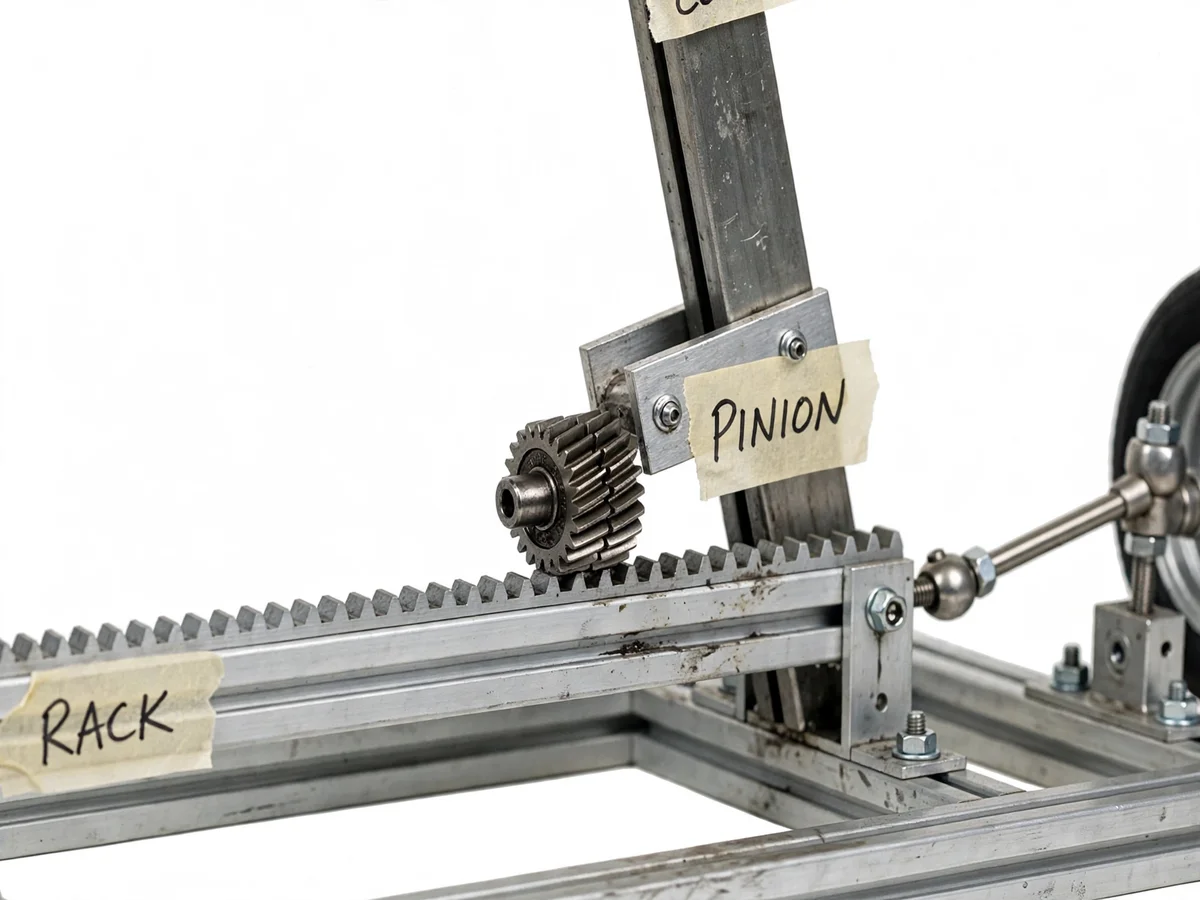
- The pinion's teeth mesh with the rack's teeth, so pinion rotation drives the rack linearly sideways along its guides.
- The rack's ends carry the inner tie-rod joints; as the rack slides, it pushes one tie rod and pulls the other.
- The tie rods act on the steering arms of the two wheel uprights, rotating both wheels about their kingpin axes.
- The ball-joint rod ends accommodate the changing angles as the geometry moves through its travel.
- Steering stops at each end of the rack limit the travel, defining the lock-to-lock range the student measures.
- Adjusting the threaded tie-rod ends changes each wheel's static toe angle, demonstrating alignment practice.
Tech stack:
- Steel pinion gear and toothed rack
- Steering wheel with column and bearings
- Tie rods with ball-joint rod ends
- Aluminium extrusion frame and brackets
- Wheel and upright assemblies
- Measuring scale and protractor (trial instruments)
| Parameter | Value |
|---|---|
| Mechanism | Rack and pinion, manual |
| Frame | Aluminium extrusion chassis (design) |
| Input | Steering wheel on bearing-supported column |
| Output | Dual-wheel steer via tie-rod linkage |
| Steering ratio | Approximately 12:1 (design target; buyer-measured) |
| Rack travel | Measured per wheel revolution (buyer-run procedure) |
| Adjustment | Threaded tie-rod ends for toe setting |
| Demo | Lock-to-lock travel and ratio measurement |
Project features
- [Real steering wheel and column] A proper steering wheel on a supported column with bearings, giving the authentic input feel of the mechanism.
- [Pinion and rack pair] A steel pinion meshing with a toothed rack, demonstrating the rotary-to-linear conversion at the heart of the system.
- [Tie-rod linkage] Tie rods with ball-joint ends connect the rack to both wheel uprights, splitting the linear travel into steering motion at each wheel.
- [Rigid aluminium frame] An aluminium extrusion chassis that holds alignment under load, so measurements are repeatable.
- [Steering-ratio measurement] A buyer-run procedure: rack travel per wheel revolution, computed into the steering ratio from the student's own readings.
- [Lock-to-lock demonstration] Full travel from one steering stop to the other, showing the total rack displacement and wheel angle range.
- [Adjustable tie-rod ends] Threaded rod ends allow toe adjustment, demonstrating how real steering geometry is set and aligned.
What is included
- Complete fabricated rack-and-pinion steering model on aluminium frame
- Steering wheel, column, pinion, rack, tie rods and wheels
- Steering-ratio and rack-travel measurement procedure (buyer-run)
- Geometry study notes (ratio, travel, toe adjustment)
- Project report PDF (steering theory, mechanism analysis, measured results)
- PPT presentation for final review
- Viva Q&A preparation document (pinion/rack kinematics, steering ratio, linkage)
Limitations & prerequisites
- The model demonstrates steering kinematics; it is not a power-steering system and makes no claim about assist forces.
- Steering-ratio and travel figures are design targets verified by the student's own measurements, not pre-claimed values.
- Exact Ackermann geometry is discussed as theory; the bench model prioritizes clear demonstration over certified geometry.
- The model is manually operated — no motor drive or automation is included.
- Long-term wear of the rack teeth under repeated demo use is a maintenance note, not a defect.
Frequently Asked Questions
How does the rack and pinion convert the motion?
The pinion is a small gear on the end of the steering column; its teeth engage the straight teeth of the rack. Rotating the pinion walks it along the rack, pushing the rack sideways — rotary motion in, linear motion out, with the gear ratio setting how far the rack moves per wheel turn.
What is the steering ratio and how do I find it?
The ratio is steering-wheel angle divided by road-wheel angle. The procedure has the student measure rack travel per wheel revolution and wheel steer angle with a protractor, then compute the ratio from their own numbers.
Why do both wheels need tie rods?
The rack produces one linear motion at the center; the tie rods split it to the left and right steering arms so both wheels steer together. The ball joints let the rods follow the geometry through full travel without binding.
Can I adjust the wheel alignment?
Yes — the tie-rod ends are threaded, so screwing them in or out changes each wheel's toe angle, exactly as on a real car. The procedure covers setting and checking it.
Is this power steering?
No — it is the manual rack-and-pinion mechanism that power steering assists. Understanding this manual core first is precisely what makes power-steering theory (hydraulic or electric assist) easy afterwards.
Is this project suitable for a final-year project?
Yes — for Mechanical Engineering programs. It is a working mechanism study: kinematics, steering ratio measurement, linkage geometry and alignment practice. Suitable for B.E./B.Tech final-year projects in Mechanical Engineering.
Components & software requirements
- Steel pinion gear and toothed rack
- Steering wheel with column and bearings
- Tie rods with ball-joint rod ends
- Aluminium extrusion frame and brackets
- Wheel and upright assemblies
- Measuring scale and protractor (trial instruments)
Delivery information
Built-to-order project. Delivery timeline is shared after order confirmation based on current queue.
Support terms
Complete documentation, setup guide, and viva preparation included. Support for setup and explanation provided.