
More project photos (2)
The problem
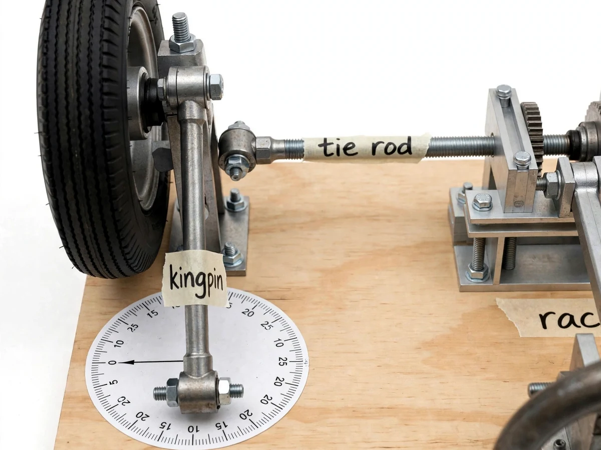
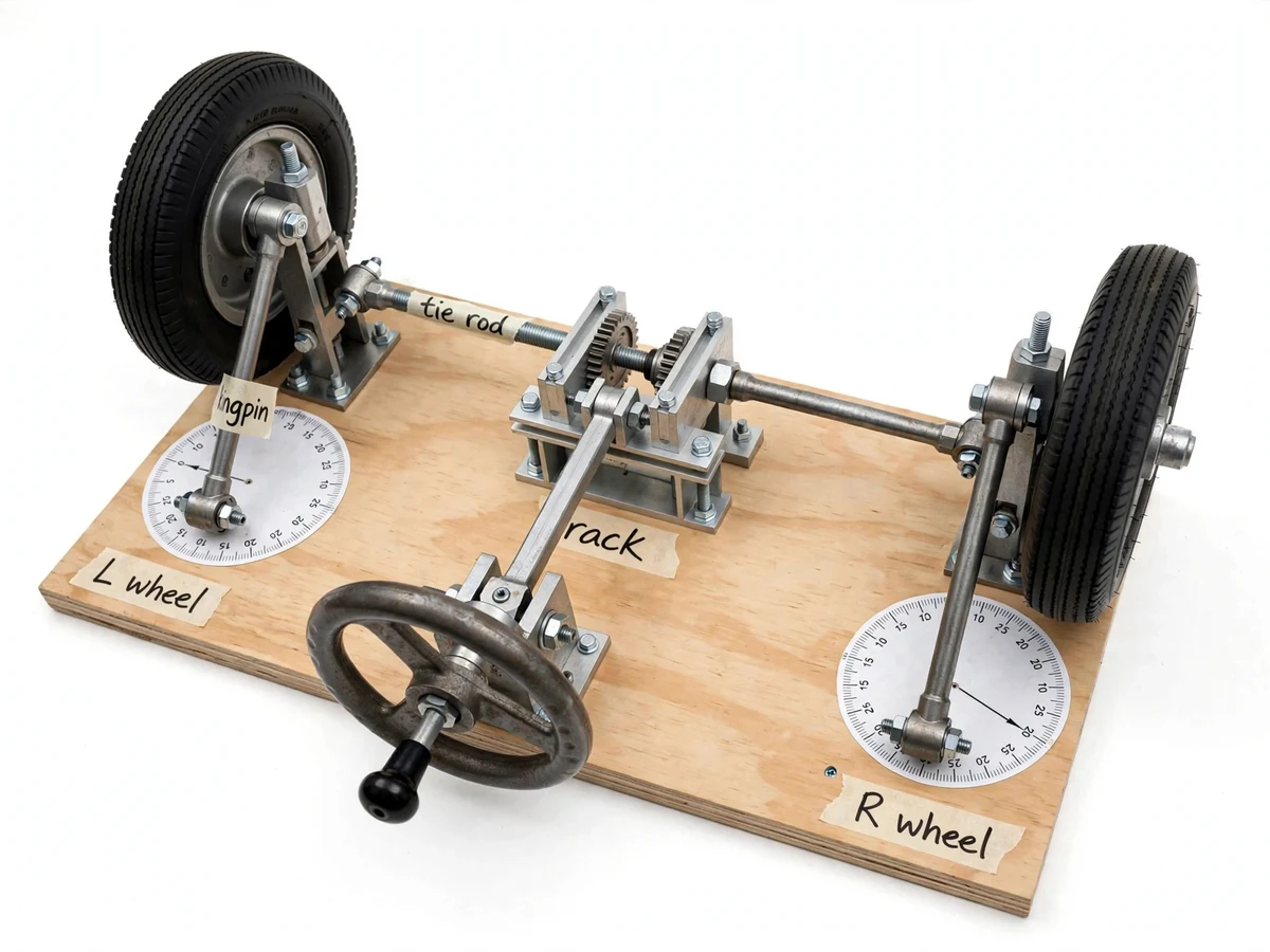
Every car steers with its front wheels at different angles — the inner wheel turns more sharply than the outer so both roll without scrubbing — yet most students meet this Ackermann geometry only as a line diagram with an instant-centre construction. Whether real hardware actually produces those angles, and how far a simple linkage deviates from the ideal, is never checked. This project makes the geometry measurable: a bench rig with two rubber-tyred wheels on kingpin mounts, linked by a tie rod to a central rack-and-pinion block driven by a hand steering wheel. Printed protractor dials under each wheel let the student read both steer angles at any steering input and compute the error against the theoretical Ackermann angles for the rig's track and wheelbase. The deviation curve — measured versus ideal — becomes the student's own experimental result, and the classic Davis-vs-Ackermann discussion finally has numbers behind it.
How it works
- The student turns the hand steering wheel, which drives the pinion and slides the rack sideways.
- The rack pushes/pulls the tie rod, which rotates both wheel assemblies about their kingpins through the steering arms.
- Because the steering arms are angled per the Ackermann layout, the inner wheel rotates through a larger angle than the outer wheel.
- At a chosen steering input, the student reads the inner angle from the left dial and the outer angle from the right dial.
- The theoretical Ackermann angles are computed from the rig's measured track width and wheelbase using the cotangent relationship.
- Measured and theoretical angles are tabulated across several steering inputs, and the error at each input is plotted.
- The tie-rod length is adjusted and the test repeated, showing how linkage tuning moves the measured curve toward or away from ideal.
Tech stack:
- Steel/wood bench frame with two wheel stations
- Rack-and-pinion steering block with hand wheel
- Tie rod with turnbuckle adjustment, steering arms
- Kingpin wheel mounts with ball bearings
- 2× rubber-tyred wheels
- Printed protractor dials (0–40° range, design)
- Handwritten labels, assembly documentation
| Parameter | Value |
|---|---|
| Steering input | Hand wheel → rack and pinion (design) |
| Angle readout | 2× printed protractor dials, 0–40° range (design) |
| Wheels | 2× rubber-tyred, kingpin-mounted (design) |
| Linkage | Tie rod with turnbuckle adjustment (design) |
| Track / wheelbase | Measured by the student on their build (not pre-claimed) |
| Angles | Measured per input vs theoretical Ackermann values |
| Base | Plywood bench board (design) |
| Drive | Manual (no motor, no electrics) |
Project features
- [Hand-cranked steering input] A steering wheel on a column drives the rack-and-pinion block, giving smooth, controllable steer-angle input the student can hold at any position for reading.
- [Dual protractor dials] Printed angle dials under each wheel let inner and outer steer angles be read directly — no estimation, no protractor juggling.
- [Tie-rod and kingpin linkage] Real steering hardware (tie rod, steering arms, kingpin mounts) reproduces the actual Ackermann linkage rather than a simplified model.
- [Labeled components] Handwritten masking-tape labels mark the tie rod, kingpin, rack and L/R wheels for clear demonstration.
- [Ackermann verification procedure] A student-run worksheet: set steering input, read both angles, compute theoretical Ackermann angles from track and wheelbase, record the error.
- [Adjustable tie-rod length] Turnbuckle-style adjustment lets the student see how linkage tuning changes the angle relationship.
- [Rubber-tyred wheels] Real rolling wheels on the dials make the no-scrub rolling condition intuitive during demonstration.
What is included
- Fabricated Ackermann steering rig (frame, wheels, rack-and-pinion, tie rod, dials, hand wheel)
- Printed protractor dials fitted under each wheel
- Angle-measurement worksheet with blank observation table
- Assembly and adjustment notes
- Project report PDF (Ackermann theory, Davis comparison, cotangent relationship, methodology)
- PPT presentation for final review
- Viva Q&A preparation document (Ackermann condition, instant centre, steering errors)
Limitations & prerequisites
- Steer angles are measured by the student on their own build — no angle values are claimed in advance; accuracy depends on the student's dial reading (typically ±0.5°).
- The rig is a kinematic demonstrator: it does not model tyre slip angles, suspension compliance or dynamic load transfer.
- The linkage approximates Ackermann geometry; the measured-vs-theoretical error curve is the honest result, not a perfect match — the report treats the deviation as the finding.
- Manual input only — there is no motorized or powered-steering variant in this build.
- Dial zeroing must be checked before each test series per the procedure; a bumped dial gives a shifted reading.
Frequently Asked Questions
What is the Ackermann condition?
When steering, the inner wheel must turn through a larger angle than the outer so that all wheels roll about a common instant centre without scrubbing. The rig shows this happening and lets the student measure both angles.
How are the theoretical angles computed?
From the rig's track width and wheelbase using the cotangent relationship (cot δo − cot δi = track/wheelbase). The worksheet walks through the calculation.
Why won't the measured angles match theory perfectly?
Real linkages approximate the ideal — manufacturing tolerances, joint play and the tie-rod setting all add error. Plotting measured versus ideal and discussing the gap is the experiment's honest core.
What does the tie-rod adjustment demonstrate?
Lengthening or shortening the tie rod changes the angle relationship; the student can tune toward the ideal curve and document the effect — a genuine linkage-tuning study.
Ackermann vs Davis steering — which is this?
The rig implements the Ackermann layout (angled steering arms with a tie rod behind the axle line). The report compares it with the Davis sliding-pair mechanism conceptually.
Is this project suitable for a final-year project?
Yes — for Mechanical Engineering programs. It makes a classic theory-of-machines topic measurable, with student-collected angle data and an honest error analysis. Suitable for B.E./B.Tech final-year projects in Mechanical Engineering.
Components & software requirements
- Steel/wood bench frame with two wheel stations
- Rack-and-pinion steering block with hand wheel
- Tie rod with turnbuckle adjustment, steering arms
- Kingpin wheel mounts with ball bearings
- 2× rubber-tyred wheels
- Printed protractor dials (0–40° range, design)
- Handwritten labels, assembly documentation
Delivery information
Built-to-order project. Delivery timeline is shared after order confirmation based on current queue.
Support terms
Complete documentation, setup guide, and viva preparation included. Support for setup and explanation provided.