
More project photos (2)
The problem
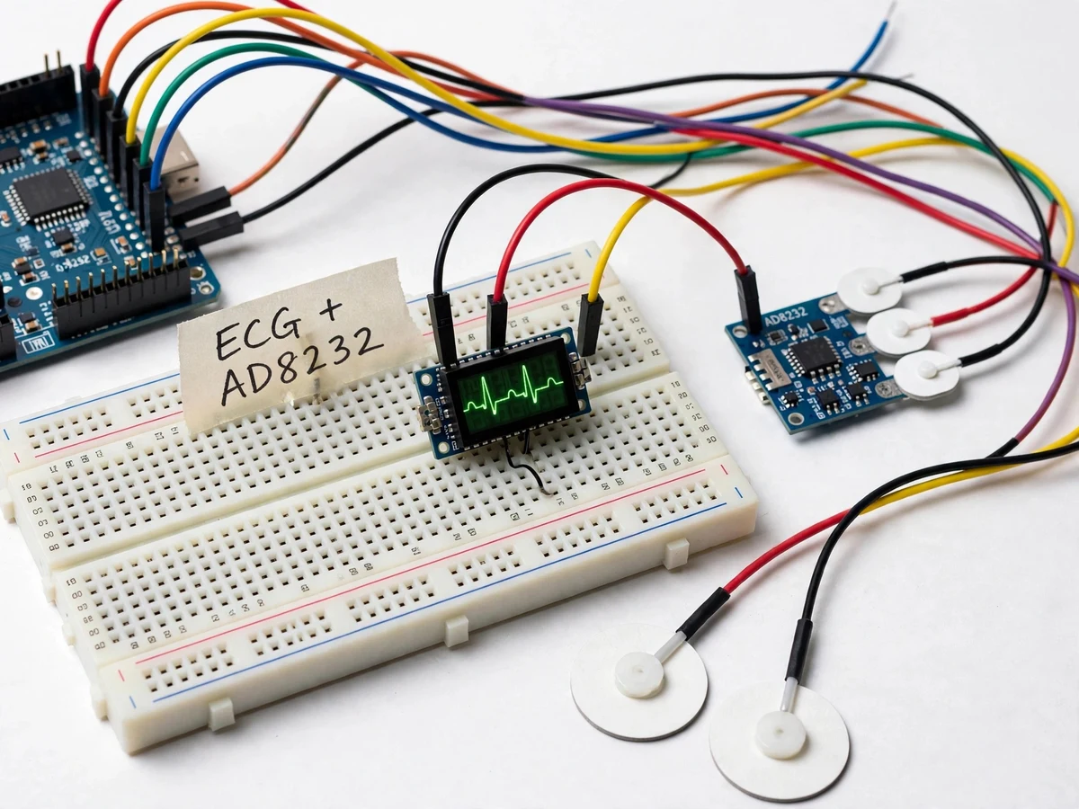
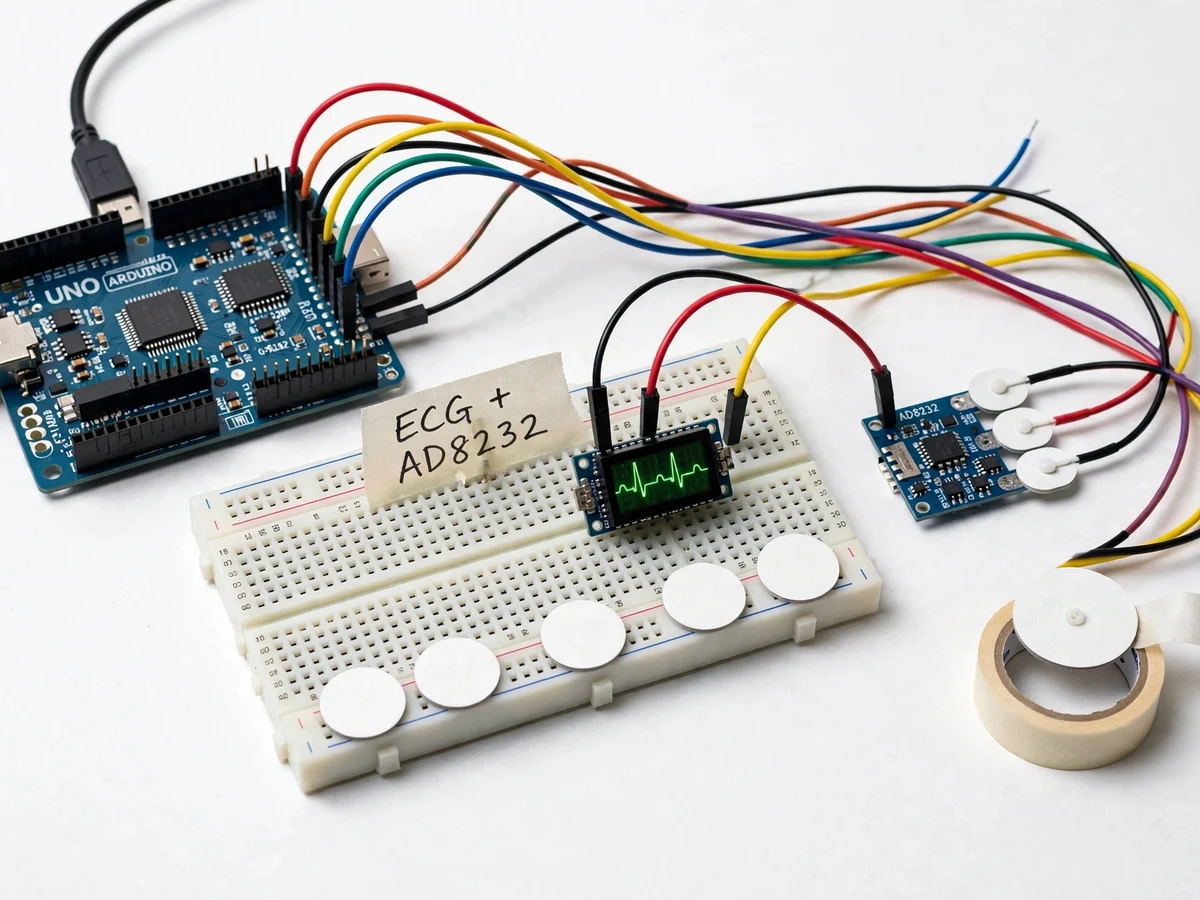
This project builds a working single-lead electrocardiograph: an Arduino Uno reads the heart's electrical signal through an AD8232 ECG sensor module and displays the live waveform on a 0.96-inch OLED screen with a heart-rate readout in beats per minute. The real engineering challenge is scale — the signal at the skin is roughly 1 mV (design-level figure), while the body also picks up mains interference many times larger, and the DC offset from electrode gel can reach ±300 mV (datasheet value). The AD8232 solves this with a classic analog chain: an instrumentation amplifier with a gain of 100 (datasheet value) rejects what both electrodes see in common, and a right-leg-drive amplifier actively cancels the 50 Hz mains hum before it swamps the trace. Three adhesive gel electrodes, a small breadboard circuit and firmware that samples, peak-detects and plots the waveform complete the build. It is designed strictly as an academic prototype for learning biopotential signal conditioning — not as certified medical equipment.
How it works
- Three adhesive gel electrodes are placed on the chest or forearms with the 3-wire lead snapped on — electrode placement and fresh gel contact is the single biggest factor in trace quality, and beats any firmware tweak.
- The AD8232's instrumentation amplifier reads the differential signal between two electrodes at a gain of 100 (datasheet value), tolerating up to ±300 mV of skin-electrode DC offset (datasheet value).
- The right-leg-drive circuit senses common-mode mains interference and drives its inverse into the third electrode, cancelling most 50 Hz hum before amplification.
- Two-pole high-pass and three-pole low-pass filter stages inside the AD8232 shape the signal band; the rail-to-rail output feeds Arduino analog pin A0.
- The Arduino samples the output at approximately 100 samples per second (design target) and pushes the points to the OLED as a scrolling trace over I2C.
- An R-peak detector (threshold crossing with refractory lockout) measures beat-to-beat intervals and converts the rolling average of the last 8 beats (design target) into beats per minute on the display.
- The firmware polls the LO+ and LO− leads-off pins continuously; if either flags, the waveform pauses and the display notes the electrode check until contact is restored.
Tech stack:
- Arduino Uno (ATmega328P)
- AD8232 single-lead ECG module
- 0.96-inch OLED · I2C (SSD1306)
- Arduino IDE · C++ firmware
- 3-wire ECG electrode lead + gel electrodes
- USB serial link (debug + plotter)
| Parameter | Value |
|---|---|
| Controller | Arduino Uno, ATmega328P, 5 V logic |
| ECG front end | AD8232 module (datasheet supply: 2.0–3.5 V) |
| Signal chain | Instrumentation amp, gain 100 (datasheet) · 2-pole high-pass · 3-pole low-pass · right-leg drive |
| Common-mode rejection | 80 dB, dc to 60 Hz (datasheet value) |
| Quiescent current | 170 µA typical (datasheet value, AD8232 only) |
| Electrode input | 3 adhesive gel electrodes, single-lead (2- or 3-electrode configuration) |
| Sampling | Approximately 100 samples/second (design target, firmware) |
| Display | 0.96-inch OLED, 128 × 64 pixels, I2C interface |
| Heart-rate output | Beats per minute from R-peak intervals (design target: rolling average of last 8 beats) |
| Power | USB 5 V from a laptop or 5 V adapter (expected) |
| Leads-off detection | LO+ / LO− pins polled by firmware (datasheet feature) |
| Fast restore | Filter-settling recovery circuit (datasheet behavior) |
Project features
- [Single-lead ECG acquisition] The AD8232 module picks up surface biopotentials of roughly 1 mV (design-level figure) through three adhesive gel electrodes, with a datasheet instrumentation-amplifier gain of 100 and acceptance of up to ±300 mV of electrode DC offset.
- [Right-leg-drive mains rejection] The AD8232's right-leg-drive amplifier senses the body's common-mode voltage and drives an inverted copy back into the right-leg electrode, actively cancelling 50 Hz mains hum before it swamps the heart signal; the instrumentation amplifier (80 dB CMRR from dc to 60 Hz, datasheet value) then amplifies only the differential — the actual heartbeat.
- [Live OLED waveform] A 0.96-inch 128 × 64 OLED draws a scrolling real-time ECG trace fed by the Arduino sampling the AD8232 output at approximately 100 samples per second (design target), so the P-QRS-T morphology is visible during the demo.
- [R-peak heart-rate readout] Firmware detects R-peaks with a threshold crossing plus a refractory lockout and computes beats per minute over a rolling window of the last 8 beats (design target), shown beside the waveform.
- [Leads-off detection] The AD8232's LO+ and LO− pins flag the moment an electrode peels or loses contact; firmware pauses the trace and notes the electrode check instead of flatlining silently — a strong viva talking point.
- [Fast-restore after motion] When electrode movement saturates the filter stages, the AD8232's fast-restore circuit shortens the settling time so the trace recovers in a fraction of a second instead of drifting (datasheet behavior).
- [Serial plotter debugging] Raw samples stream over USB to the Arduino IDE serial plotter, giving a second large-screen view of the waveform for calibration and viva demonstration.
What is included
- Assembled and tested prototype (Arduino Uno, AD8232 module, OLED, 3-wire electrode lead, breadboard wiring)
- Complete firmware source code (Arduino IDE, commented)
- Wiring diagram and component list
- Electrode placement and skin-preparation guide (placement and gel contact quality is the single biggest factor in trace quality)
- Project report PDF (background, AD8232 signal-chain theory, methodology, results)
- PPT presentation for final review
- Viva Q&A preparation document (instrumentation amplifiers, right-leg drive, ECG basics, leads-off detection)
Limitations & prerequisites
- This is an academic prototype and is not intended to replace certified medical equipment, professional diagnosis or clinical decision-making; the BPM readout must never be used for health decisions.
- The signal is motion-sensitive: talking, walking or tensed muscles during measurement degrade the trace (design behavior of any skin-electrode ECG).
- Single-lead only — it shows rhythm and rate, not the 12-lead views clinicians use for diagnosis.
- Hum rejection depends on good electrode contact; dry skin or a peeling electrode lets 50 Hz interference overwhelm the trace.
- The BPM figure is an algorithmic estimate (design target: rolling 8-beat average) and is not validated for arrhythmia detection.
- Typical gel electrodes are single-use consumables (expected: a fresh set per demo session) and the module needs the board's 3.3 V rail within the 2.0–3.5 V datasheet supply range.
Frequently Asked Questions
Is this project suitable for a final-year project?
Yes — for Electronics & Telecommunication and Electronics & Instrumentation programs. It demonstrates analog signal conditioning (instrumentation amplifiers, filtering, right-leg drive), biopotential acquisition and embedded firmware in one physical build, with plenty of viva depth.
Which controller is used, and can it be changed?
Arduino Uno is the base build. An Arduino Nano works with the same firmware as an optional customization (same 5 V-tolerant wiring); an ESP32 port needs level shifting for the 3.3 V ADC and is also possible on request.
Does it work without Wi-Fi?
Yes — everything runs offline on the Arduino. The OLED shows the trace and BPM, and the USB serial plotter is only an optional debugging view. There is no cloud or app component in the base build.
What are the main limitations?
It is an academic prototype, not a medical device; the trace is motion-sensitive; it is single-lead (rhythm and rate only); and good electrode gel contact is essential. The full honest list is under Limitations above.
Can Bluetooth or a phone app be added?
As an optional customization — an HC-05 module can stream BPM and raw samples to a phone app. It is not part of the base prototype.
What power supply is needed?
USB 5 V from a laptop or a 5 V adapter (expected); the AD8232 module itself runs from the board's 3.3 V rail, inside its 2.0–3.5 V datasheet supply range.
Components & software requirements
- Arduino Uno (ATmega328P)
- AD8232 single-lead ECG module
- 0.96-inch OLED · I2C (SSD1306)
- Arduino IDE · C++ firmware
- 3-wire ECG electrode lead + gel electrodes
- USB serial link (debug + plotter)
Delivery information
Built-to-order project. Delivery timeline is shared after order confirmation based on current queue.
Support terms
Complete documentation, setup guide, and viva preparation included. Support for setup and explanation provided.
Download free synopsis (PDF)
Enter your name and WhatsApp number — the synopsis PDF downloads immediately. We may send occasional project updates on WhatsApp; no spam.