
More project photos (3)
The problem
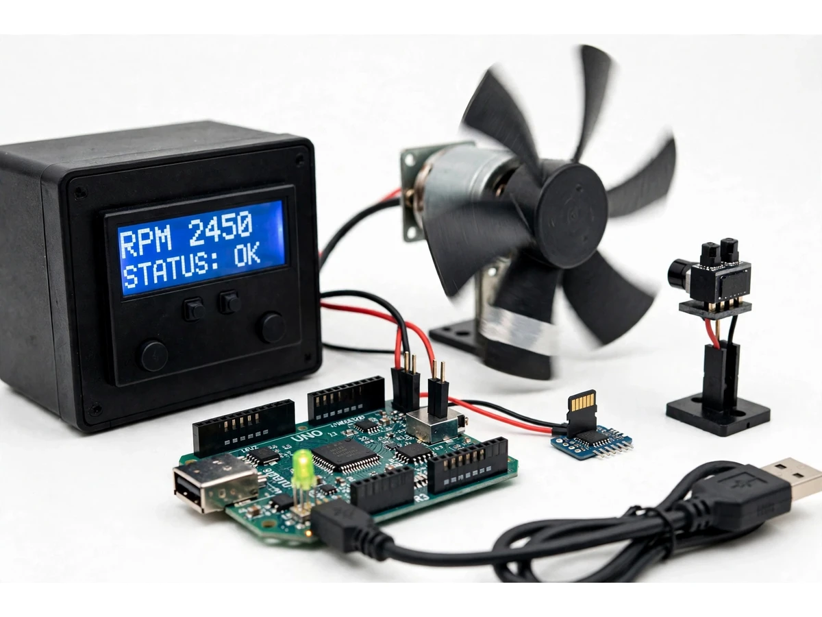
An Arduino-based digital tachometer with an IR sensor and RPM data logging measures how fast a shaft or fan rotates without touching it, and records those readings over time. It is built around an Arduino Uno, a reflective IR sensor aimed at a marked rotor, a 16x2 LCD for live readings, push buttons for hold and peak modes, and an SD-card module that stores timestamped RPM values. The need it answers is practical: workshops, laboratories and student test benches often need a repeatable speed reading for motors, fans and small spindles, but hand counting and stopwatch timing are slow and inconsistent, and visual estimation is useless once the shaft stops turning. A contact tachometer avoids guessing, yet it must touch the shaft, which is awkward on small, hot or guarded rotors. This project instead counts real revolutions optically, converts pulse timing into revolutions per minute, and keeps a log that can be opened and compared after the run.
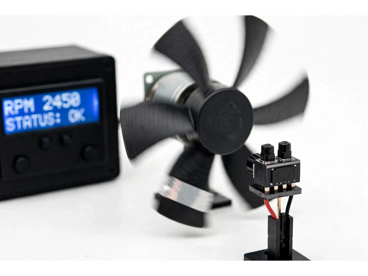
Concept: one reflective mark, one pulse per revolution, timed precisely. A single strip of reflective tape on an otherwise dark rotor passes the IR sensor once per turn, so each pulse marks exactly one revolution; the Arduino measures the time between pulses, converts it to revolutions per minute, and shows and logs the result. This is a measurement instrument, not a visual trick: unlike a stroboscope, which freezes motion by flashing light at a matching rate, this tachometer counts actual revolutions and produces numbers that can be stored, plotted and checked.
Builder note from the bench build: the mark must contrast sharply with the rotor, and the sensor must be shielded from stray light. A matte black rotor with one clean white reflective strip gives a crisp pulse edge, while a glossy or patchy surface returns weak, uneven reflections. Overhead tube light and direct sunlight also leak into an unshielded sensor and add false pulses, so the sensor sits inside a short opaque hood and is aimed squarely at the mark's path. In first-principles terms, the instrument is a period meter: it does not see speed directly, it times the gap between identical events and inverts that period into a rate.
One white strip on a dark rotor passes the sensor once per revolution.
Follow the working sequence
How it works
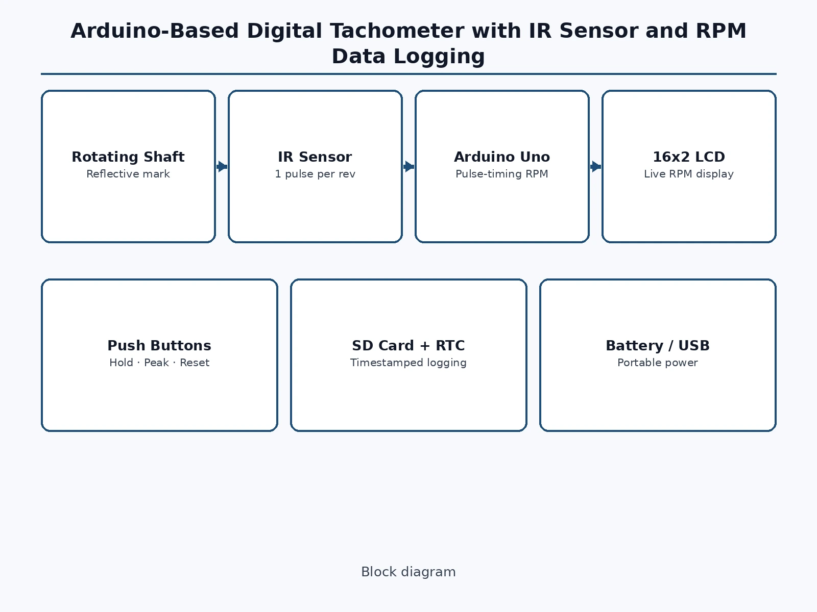
The tachometer turns rotation into a number through a short, repeatable chain. A single reflective mark on a dark rotor passes the IR sensor once per revolution, and the sensor emits one clean pulse for each pass. The Arduino records the time of each pulse with its microsecond timer, measures the interval between successive pulses, and converts that interval into revolutions per minute by dividing 60 seconds by the period in seconds. A short rolling average steadies the displayed value against single-pulse jitter, the 16x2 LCD shows the current RPM continuously, and the SD-card module writes timestamped samples at the set logging interval. Push buttons interrupt nothing in this chain: hold freezes only the displayed value, and peak simply remembers the largest computed value since reset. Because the method times real events rather than estimating from appearance, the displayed number stays valid even when the rotor spins too fast for the eye to follow.
- A single strip of reflective tape is fixed on the rotor, and the rest of the rotor surface is kept dark so the mark stands out sharply.
- The IR sensor, shielded by a short opaque hood against stray light, is aimed at the mark's path at the sensor's working distance.
- Each time the mark passes, the sensor outputs one pulse; the Arduino timestamps the pulse edge with its microsecond timer.
- Firmware computes RPM from the interval between the two most recent pulses (60 divided by the period in seconds), smoothed by a short rolling average.
- The 16x2 LCD updates continuously with the current RPM, and the hold and peak buttons freeze the display or recall the fastest value since reset.
- At the set logging interval, the current RPM and the real-time-clock timestamp are appended as one row to a file on the microSD card.
- After the run, the card is read on a computer and the logged rows are opened in a spreadsheet for comparison and reporting.
Tech stack:
- Arduino Uno · ATmega328P
- Arduino IDE · C++ firmware
- IR reflective sensor module
- 16x2 character LCD · I2C
- MicroSD card module · SPI
- DS3231 real-time-clock module
- Push-button hold · peak controls
- Battery · USB power
| Parameter | Value |
|---|---|
| Controller | Arduino Uno, ATmega328P at 16 MHz clock (datasheet value) |
| Sensing method | Reflective IR sensor, 1 pulse per revolution (design configuration) |
| Display | 16 characters × 2 lines LCD with I2C interface |
| RPM display range | 60 RPM to 10,000 RPM (design target, not a measured claim) |
| RPM calculation | Pulse-period timing, 60 divided by period in seconds, with rolling average |
| Timer resolution | 4 microseconds (Arduino micros() documented resolution) |
| Low-speed behaviour | Below approximately 60 RPM, updates arrive slower than 1 per second because pulses arrive less than once per second (design behaviour) |
| High-speed limit | Above the design target, the practical limit is sensor switching and mark dwell time, not the microcontroller clock (design explanation) |
| Logging | MicroSD card, 1 timestamped row per logging interval, timestamped by a DS3231 real-time-clock module with battery backup (design configuration) |
| Power | 5 V USB supply or battery pack (design configuration) |
Project features
The tachometer centres on four capabilities that work together: non-contact RPM measurement from a reflective mark, a live 16x2 LCD readout, hold and peak capture through push buttons, and timestamped SD-card logging for later analysis. The IR sensor watches the marked rotor and sends one pulse per revolution, the Arduino times those pulses and converts them into revolutions per minute, and the LCD updates continuously so speed changes are visible as they happen. When a reading must be kept, the hold button freezes the displayed value, and the peak button recalls the fastest speed seen since the last reset. Every logged sample carries a real-time-clock timestamp, so a run can be reviewed, compared with a later run, and discussed with numbers rather than memory. The configurable pulses-per-revolution setting extends the same counting logic to multi-mark rotors, and battery or USB power keeps the unit portable for checks away from the bench.
- [Non-contact RPM measurement] The reflective IR sensor faces the marked rotor and produces one pulse per revolution, so speed is measured without touching, loading or slowing the shaft. Implemented in the base build.
- [Live 16x2 LCD readout] Current RPM is shown continuously on a 16x2 character LCD, with a second line for mode and status, so the reading stays visible throughout a run. Implemented in the base build.
- [Pulse-timing RPM calculation] The Arduino measures the interval between successive pulses and converts it to revolutions per minute, with a short rolling average that steadies the display without hiding genuine speed changes. Implemented in the base build.
- [Hold and peak modes] One push button freezes the displayed reading for noting down, another recalls the highest RPM recorded since the last reset, and a reset clears the peak value. Implemented in the base build.
- [SD-card logging with timestamps] Each logged sample is written to a microSD card as a timestamped RPM row from the real-time-clock module, so runs can be opened in a spreadsheet and compared afterwards. Implemented in the base build.
- [Configurable pulses per revolution] The pulses-per-revolution setting in firmware can be changed for rotors carrying more than one mark, so the same unit can measure multi-blade fans and multi-mark shafts correctly. Configurable in the base build.
- [Battery or USB power] The unit runs from USB during bench use or from a battery pack for portable checks, so it can be carried to a motor, fan or test rig instead of bringing the rig to a bench. Implemented in the base build.
Optional customizations (not in the base build): Bluetooth or serial output to a computer for live plotting, a larger graphical display, and an enclosure with a fixed sensor bracket. Future scope (not implemented): automatic RPM-versus-time graphing on the device itself, closed-loop motor speed control, and wireless logging to a phone app.
What is included
- Assembled and tested tachometer prototype (Arduino, IR sensor, 16x2 LCD, push buttons, SD-card module, real-time-clock module)
- Complete firmware source code with the pulses-per-revolution setting documented
- Circuit and wiring documentation with sensor aiming and shielding notes
- Component list with the rotor-marking procedure
- Setup and operating guide covering hold, peak, reset and SD-card reading
- Project report PDF (background, sensor theory, pulse-timing method, methodology, limitations)
- PPT presentation for final review
- Viva Q&A preparation document (IR sensing, pulse timing, averaging, logging, measurement limits)
Timeline
- Week 1: requirements, sensor and LCD interfacing, and pulse-timing firmware on the bench.
- Week 2: hold and peak modes, push-button handling, and LCD display layout.
- Week 3: SD-card logging with real-time-clock timestamps and spreadsheet-readable output.
- Week 4: shielding and marking trials, full-run testing, documentation, report, PPT and viva Q&A.
Support
- Setup guidance for wiring, sensor aiming, rotor marking and first run, a walkthrough of hold, peak, reset and log reading, and fixes for defects found in the shipped build during the handover review.
Requirements
- Arduino IDE on a computer for firmware upload and serial monitoring
- USB cable and 5 V USB supply, or a battery pack for portable use
- A motor, fan or shaft rig with a surface that accepts one reflective mark
- A microSD card and a computer with a card reader or spreadsheet app for reading logs
- No internet connection, paid service or cloud subscription is required for the base build
Limitations & prerequisites
- The unit measures only rotors that can carry a reflective mark; transparent, mirror-polished or fully white rotors need a darkened patch first.
- Strong stray light (direct sunlight, unshielded tube light on the sensor) can add false pulses; the hood and dark rotor surface are part of the correct setup, not optional extras.
- Below approximately 60 RPM the display updates slowly because pulses arrive less than once per second; this is a property of period measurement, not a fault.
- Above the 10,000 RPM design target, sensor switching speed and the mark's dwell time in front of the sensor set the practical limit, and readings beyond the target are not claimed.
- Logged timestamps depend on the real-time-clock battery; a flat backup cell gives wrong dates until it is replaced and the clock is reset.
- This is an academic bench instrument, not a certified industrial tachometer, and it must not be used where a certified measurement is legally or contractually required.
- The SD card must be formatted as FAT32; cards in other formats are not read by the logging module.
Frequently Asked Questions
Is this project suitable for a final-year project?
Yes, this project fits Electronics and E&TC programmes because it combines sensor interfacing, timer-based measurement, display driving, push-button input and SD-card logging in one working bench instrument that gives a student real measurement concepts to explain and defend in a review. It covers how a reflective sensor produces pulses, how pulse timing becomes RPM, why averaging steadies the display, and where the measurement limits come from. The report walks through each part in turn, so review questions can be answered from the built instrument rather than from generic descriptions.
How does the tachometer measure RPM without touching the shaft?
It counts real revolutions optically: one reflective mark on a dark rotor passes the IR sensor once per turn, each pass produces one pulse, and the Arduino measures the time between successive pulses and converts that period into revolutions per minute. The result is a counted measurement rather than an estimate. Because nothing touches the shaft, the instrument neither loads the motor nor needs access to a shaft end, which is why it suits small, hot or guarded rotors.
What RPM range can it measure?
The design target is 60 RPM to 10,000 RPM, which covers common small motors, fans and bench spindles, and readings outside that range are not claimed because sensor switching speed and mark dwell time set the practical ceiling above the target. At 10,000 RPM with one mark per revolution, pulses arrive every 6 milliseconds, which the microcontroller timer resolves comfortably. Below 60 RPM, pulses arrive less than once per second, so the display simply updates more slowly; that is an honest property of period measurement.
How is this different from a stroboscope?
A stroboscope freezes motion visually by flashing light at a matching rate, while this tachometer counts actual revolutions and reports a counted number, storing timestamped RPM rows on an SD card that can be reopened, plotted and compared after the run. The difference matters for records: a stroboscope reading depends on the observer judging when motion appears frozen. For a project report, counted and logged numbers are stronger evidence than a visual impression of frozen motion.
What do the logged files contain, and how do I read them?
Each logged row contains a real-time-clock timestamp and the RPM value at that moment, stored as plain text on the microSD card so the file opens directly in a spreadsheet without special software, for plotting, averaging or comparing runs side by side. No special software is needed beyond a card reader and a spreadsheet app, and the operating guide shows the exact steps for removing, reading and reinserting the card.
Can this project be customized?
Yes, realistic customizations include Bluetooth or serial output for live plotting on a computer, a larger graphical display, and an enclosure with a fixed sensor bracket, each built as a separate addition to the working base instrument rather than promised inside it. The base build stays deliberately focused on accurate measurement, display and logging, so a customization is quoted and built on top of a working instrument. A student can also change the pulses-per-revolution setting for multi-mark rotors, and the report documents where that setting lives in the firmware.
Components & software requirements
- Arduino Uno · ATmega328P
- Arduino IDE · C++ firmware
- IR reflective sensor module
- 16x2 character LCD · I2C
- MicroSD card module · SPI
- DS3231 real-time-clock module
- Push-button hold · peak controls
- Battery · USB power
Delivery information
Built-to-order project. Delivery timeline is shared after order confirmation based on current queue.
Support terms
Complete documentation, setup guide, and viva preparation included. Support for setup and explanation provided.
Download free synopsis (PDF)
Enter your name and WhatsApp number — the synopsis PDF downloads immediately. We may send occasional project updates on WhatsApp; no spam.