
More project photos (2)
The problem
Cams convert rotation into precisely timed linear motion — valve trains, automated machinery and packaging lines all depend on them — and the displacement diagram (follower lift versus cam angle) is the document that describes what a cam does. Students usually draw these diagrams from formulas for standard motions (uniform velocity, SHM, cycloidal) without ever measuring one from real hardware, so the connection between the machined profile and the plotted curve stays theoretical. This project closes the loop physically: the student cranks an aluminium cam disc round in measured angular steps, reads follower lift on a dial gauge at each step, and plots the measured displacement diagram point by point. Swapping in the second cam profile and re-plotting shows how profile shape becomes motion law — the eccentric cam's smooth rise versus the snail cam's sudden drop are felt through the crank and seen on the gauge. The measured curve, with its real-world wiggles, is the student's own experimental result.
How it works
- The eccentric cam disc is fitted to the shaft and the dial gauge is zeroed with the follower on the cam's base circle.
- The student turns the hand crank in 15° increments (marked on the procedure's angle column) and records the dial-gauge reading at each step for one full revolution.
- The 24 readings are plotted as follower displacement versus cam angle — the measured displacement diagram for the eccentric cam.
- Rise, dwell and return regions are identified on the plotted curve and compared with the theoretical expectation for an eccentric profile.
- The cam is swapped for the snail profile, the gauge re-zeroed, and the stepped measurement repeated.
- Both measured curves are plotted on the same axes, and the differences in rise rate, maximum lift and return behaviour are discussed.
- The report compares the measured diagrams with ideal motion laws and attributes deviations (gauge least count, step size, follower play) honestly.
Tech stack:
- Aluminium cam discs, 2 profiles (eccentric + snail, design)
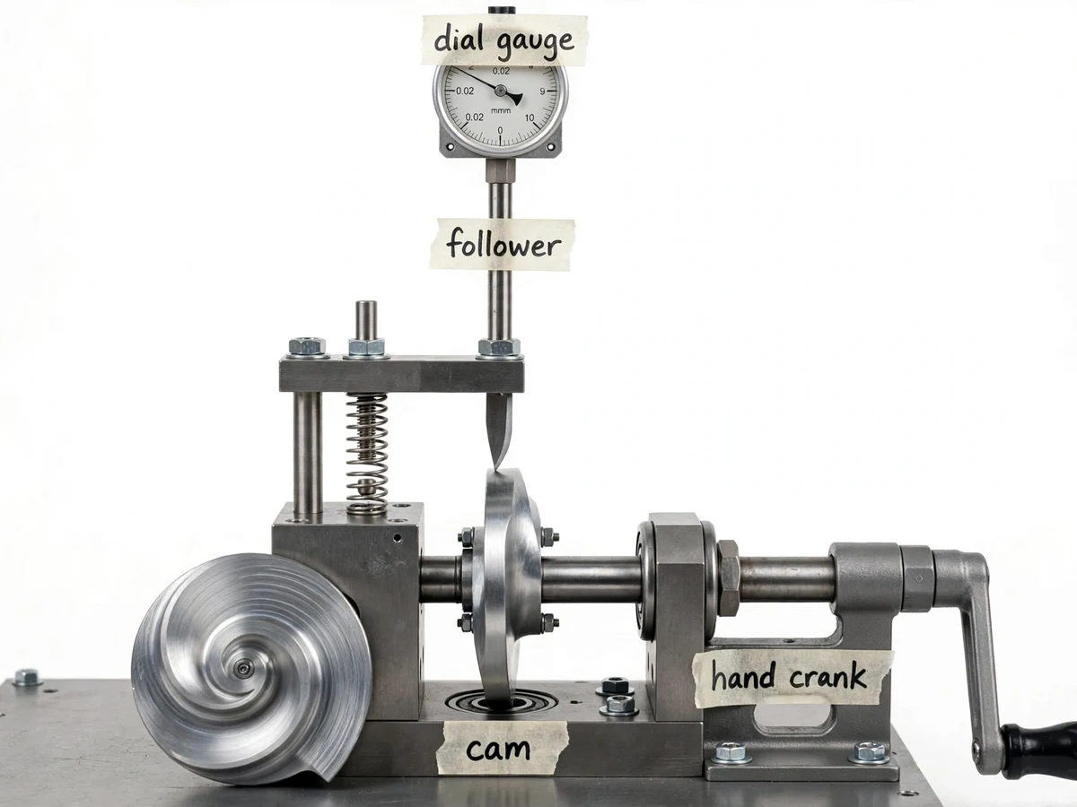
- Knife-edge follower with coil-spring return
- Dial gauge, 0–10 mm range, 0.01 mm least count (design)
- Hand crank on cam shaft
- Ball-bearing shaft supports, steel base plate
- Handwritten labels, measurement worksheet with graph sheet
| Parameter | Value |
|---|---|
| Cam profiles | 2 (eccentric + snail), aluminium (design) |
| Follower | Knife-edge, spring-loaded (force-closed) (design) |
| Displacement readout | Dial gauge, 0–10 mm, 0.01 mm least count (design) |
| Angular steps | 15° per reading, one full revolution (design) |
| Readings per cam | 24 angle–lift pairs (design) |
| Drive | Hand crank |
| Shaft supports | Ball bearings (design) |
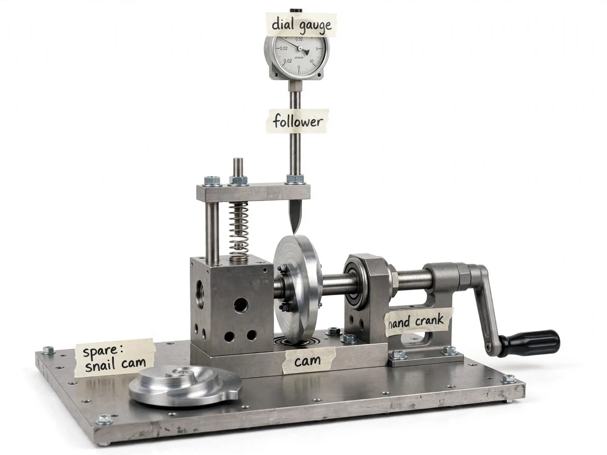
| Base | Steel plate with spare-cam storage (design) |
Project features
- [Interchangeable cam discs] Two aluminium cam profiles (eccentric and snail, design) swap onto the shaft in minutes, so profile-vs-motion comparison is the core experiment.
- [Dial-gauge displacement readout] A 0–10 mm dial gauge (design, 0.01 mm least count) above the follower reads lift directly at each angular step.
- [Stepped crank rotation] The hand crank lets the student advance the cam in fixed angular increments (15° steps per the procedure) and hold position for each reading.
- [Spring-loaded follower] A coil spring keeps the knife-edge follower in constant contact with the cam, demonstrating the force-closed follower arrangement.
- [Spare-cam storage] The unused cam profile stores on the base plate beside the rig — visible in the build and convenient during changeover.
- [Displacement-diagram worksheet] A student-run procedure with a blank angle-vs-lift table and graph sheet for plotting both cams' measured curves.
- [Labeled assembly] Handwritten masking-tape labels mark the cam, follower, dial gauge and hand crank.
What is included
- Fabricated cam-and-follower rig (shaft, follower, spring, crank, base, dial gauge)
- Two interchangeable aluminium cam discs (eccentric + snail)
- Dial gauge fitted above the follower
- Displacement-measurement worksheet with blank table and graph sheet
- Assembly and cam-changeover notes
- Project report PDF (cam theory, motion laws, displacement diagrams, methodology)
- PPT presentation for final review
- Viva Q&A preparation document (cam terminology, dwell/rise/return, follower types, pressure angle)
Limitations & prerequisites
- Displacement values are measured by the student on their own build — no lift figures are claimed in advance; the dial gauge's 0.01 mm least count sets the reading resolution.
- The 15° step size quantizes the curve; fine features between steps are not captured — the report discusses step size as a measurement choice.
- Only two cam profiles are supplied; custom profiles are future scope, not included.
- The rig measures kinematics only — cam contact forces, wear and pressure angle effects are discussed theoretically, not measured.
- Follower play and gauge hysteresis add small scatter to the readings; repeat runs are part of the procedure.
Frequently Asked Questions
What is a displacement diagram?
A plot of follower lift against cam rotation angle — the complete description of what a cam does. The student builds it point by point from dial-gauge readings instead of copying it from a book.
Why two different cam profiles?
The eccentric cam gives smooth, symmetric rise and return; the snail cam gives gradual rise with sudden drop. Measuring both shows how profile geometry becomes motion law.
How accurate are the measurements?
The dial gauge reads to 0.01 mm (design least count); the dominant limits are the 15° step size and manual crank positioning. The report treats these as the experiment's stated tolerances.
What is the spring for?
It keeps the follower pressed against the cam (force-closed follower) so contact is never lost during the return stroke — without it, the follower would bounce and the readings would be meaningless.
How do measured curves compare with theory?
The report overlays the student's measured points on ideal motion-law curves and discusses the deviations honestly — gauge resolution, step quantization and follower play.
Is this project suitable for a final-year project?
Yes — for Mechanical Engineering programs. It turns cam theory into a hands-on measurement experiment with plotted, student-collected results. Suitable for B.E./B.Tech final-year projects in Mechanical Engineering.
Components & software requirements
- Aluminium cam discs, 2 profiles (eccentric + snail, design)
- Knife-edge follower with coil-spring return
- Dial gauge, 0–10 mm range, 0.01 mm least count (design)
- Hand crank on cam shaft
- Ball-bearing shaft supports, steel base plate
- Handwritten labels, measurement worksheet with graph sheet
Delivery information
Built-to-order project. Delivery timeline is shared after order confirmation based on current queue.
Support terms
Complete documentation, setup guide, and viva preparation included. Support for setup and explanation provided.