
More project photos (2)
The problem
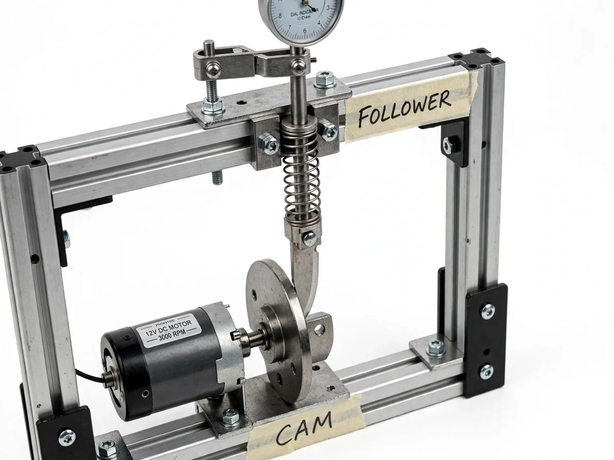
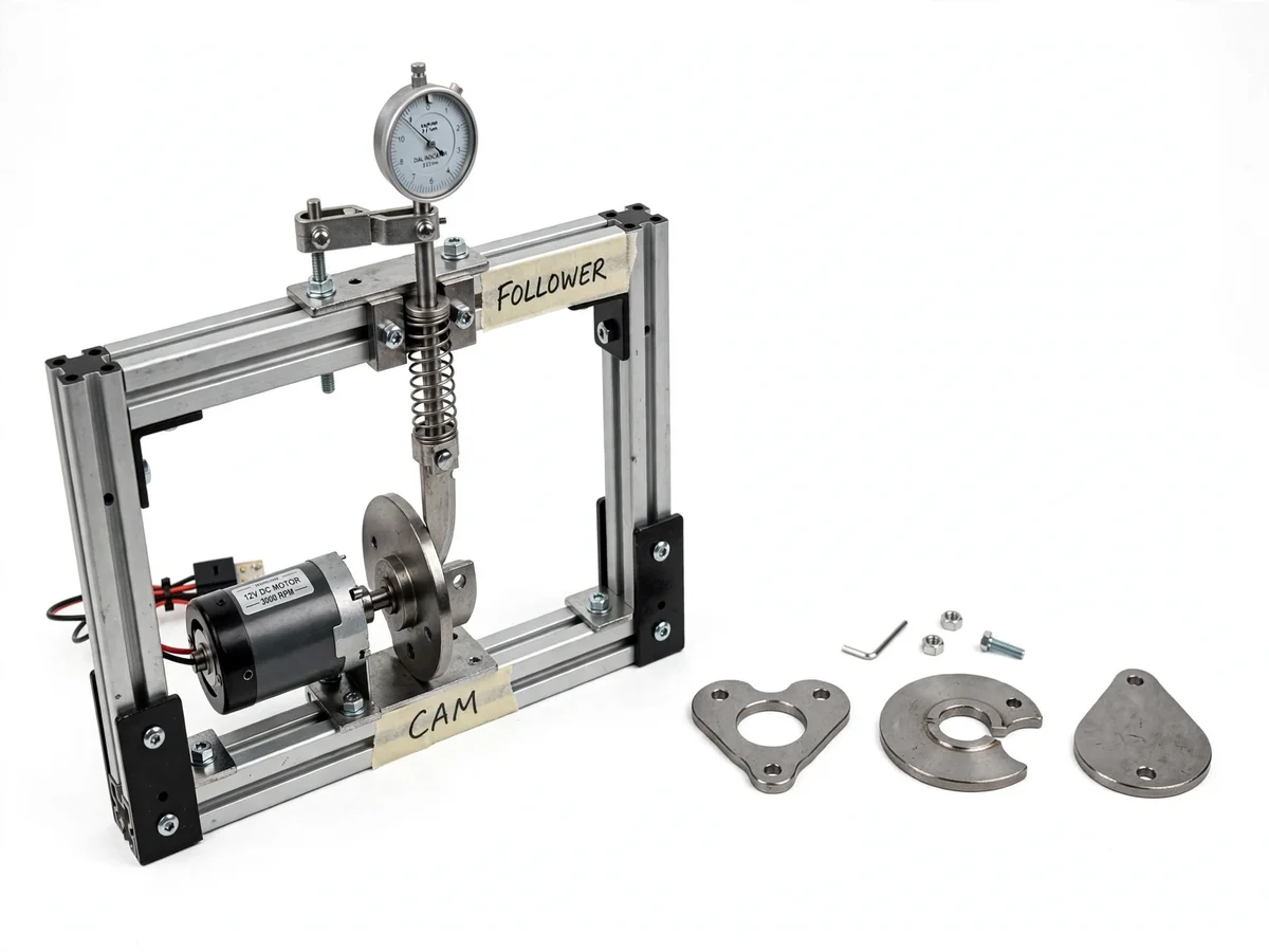
The cam and follower is the mechanism that opens engine valves, drives textile looms and times automatic machines — yet students usually meet it as a displacement curve drawn on paper, with no feeling for what the curve means on steel. This project makes the curve physical: a bench rig where a 12V DC motor drives a cam plate, a spring-loaded follower rides its edge, and a dial indicator mounted above reads the follower's lift to 0.01 mm. Three interchangeable cam profiles are supplied, so the student can watch a gentle rise, a sudden dwell and a smooth return happen in metal, then plot each cam's displacement diagram from their own dial-indicator readings taken degree by degree. The gap between the theoretical curve and the measured one — backlash, spring lag, manufacturing tolerance — becomes the most honest part of the report.
How it works
- The selected cam plate is keyed to the motor-driven shaft and locked; the follower is lowered onto the cam edge.
- The coil spring presses the follower against the cam profile, maintaining contact through the whole rotation.
- Switching on the 12V DC motor rotates the cam at a steady speed set by the controller.
- As the cam's radius under the follower grows and shrinks, the follower slides up and down in its guide.
- The dial indicator's plunger rides on the follower stem, so its needle shows the instantaneous lift in hundredths of a millimetre.
- For the displacement diagram, the student indexes the cam in fixed angular steps, records the dial reading at each, and plots lift against angle.
- Swapping to a different cam plate and repeating the procedure shows how profile shape dictates the motion law.
Tech stack:
- Machined steel cam plates (interchangeable set)
- 12V DC motor with speed control
- Spring-loaded guided follower
- Dial indicator, 0.01 mm least count
- Aluminium extrusion frame
- Degree indexing for cam angle
| Parameter | Value |
|---|---|
| Drive | 12V DC motor, approximately 3000 RPM rated (motor label) with speed control |
| Cam set | Interchangeable machined plates (design: 3+ profiles) |
| Follower | Translating, spring-loaded (force-closed) |
| Measurement | Dial indicator, 0.01 mm least count (instrument typical) |
| Diagram method | Lift recorded at fixed angular steps (buyer-run) |
| Frame | Aluminium extrusion, fixed alignment (design) |
| Supply | 12V DC adapter for motor |
Project features
- [Interchangeable cam plates] Three machined cam profiles (plus the fitted one) that swap in minutes, each producing a visibly different follower motion.
- [Motorized drive] A 12V DC motor drives the cam shaft steadily, freeing both hands for measurement — with speed control for slow study.
- [Spring-loaded follower] A guided follower held against the cam by a coil spring, demonstrating the force-closed pairing used in real machines.
- [Dial indicator measurement] A 0.01 mm-least-count dial indicator mounted over the follower reads lift directly, the honest instrument of the experiment.
- [Displacement-diagram procedure] A buyer-run method: rotate the cam in fixed angular steps, note the dial reading, and plot lift versus cam angle.
- [Dwell, rise and return observation] Each cam's profile makes one motion phase dominant, so the textbook terms become visible events.
- [Rigid aluminium frame] An extrusion frame keeps the cam shaft, follower guide and indicator in fixed alignment for repeatable readings.
What is included
- Complete fabricated cam-and-follower rig on aluminium frame
- Set of interchangeable machined cam plates
- 12V DC motor with speed controller and adapter
- Dial indicator with mounting bracket
- Displacement-diagram plotting procedure and graph sheets (buyer-run)
- Project report PDF (cam theory, motion phases, measured diagrams)
- PPT presentation for final review
- Viva Q&A preparation document (dwell/rise/return, follower types, pressure angle)
Limitations & prerequisites
- Displacement diagrams are student-measured from dial readings; the comparison with theory is honest about backlash and spring lag.
- The dial indicator measures lift only — velocity and acceleration curves are derived graphically, not sensed directly.
- Cam profiles are demonstration geometries, not certified production cams; profile tolerances are stated in the report.
- High-speed dynamics (jump, bounce) are observable qualitatively; the rig is a kinematics demonstrator, not a dynamics test cell.
- Follower and guide need occasional lubrication per the maintenance note.
Frequently Asked Questions
What do dwell, rise and return actually look like?
On the rig they are physical events: dwell is the follower sitting still while the cam turns under it, rise is the needle climbing as the profile grows, return is the needle falling back. Each supplied cam emphasizes a different phase, so the terms stop being abstract.
How do I draw the displacement diagram?
Index the cam in fixed steps (e.g. every 15–30 degrees), write down the dial-indicator reading at each step, and plot lift on the vertical axis against cam angle on the horizontal. The curve you get is the cam's motion law, measured by you.
Why does my measured curve differ slightly from theory?
Real hardware has backlash in the drive, spring lag at speed, and machining tolerance on the profile. Documenting that gap — and explaining each contributor — is exactly the analysis examiners want to see.
Why is the follower spring-loaded?
The spring keeps the follower pressed against the cam so contact is never lost — called a force-closed pair. Without it, the follower would leave the surface on the return flank and the motion would be uncontrolled.
Can I design my own cam profile?
The report documents the profile geometry of the supplied cams and the design method, so drawing and getting a custom profile machined is listed as an extension.
Is this project suitable for a final-year project?
Yes — for Mechanical Engineering programs. It is the classic theory-of-machines experiment done properly: real cams, real measurement, real displacement diagrams. Suitable for B.E./B.Tech final-year projects in Mechanical Engineering.
Components & software requirements
- Machined steel cam plates (interchangeable set)
- 12V DC motor with speed control
- Spring-loaded guided follower
- Dial indicator, 0.01 mm least count
- Aluminium extrusion frame
- Degree indexing for cam angle
Delivery information
Built-to-order project. Delivery timeline is shared after order confirmation based on current queue.
Support terms
Complete documentation, setup guide, and viva preparation included. Support for setup and explanation provided.