
More project photos (2)
Watch it work
The problem
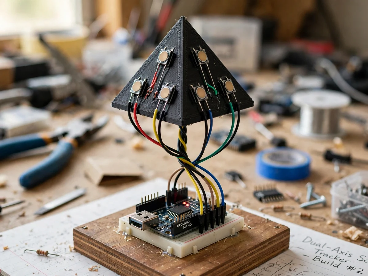
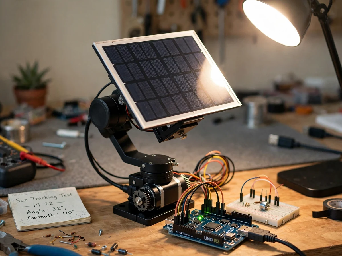
A solar panel bolted in one position only faces the sun squarely for a short part of the day. In the morning and the evening the light strikes it at a slant, and the panel collects less of the light falling on it. A tracker removes that limitation by moving the panel itself. This project builds that system at tabletop scale: four light sensors sit on a small pyramid above the panel, an Arduino compares their readings, and two motors tilt and turn the panel so it keeps facing the brightest light. A bright lamp stands in for the sun in the indoor demonstration, and the panel visibly follows the lamp from any starting angle.
How it works
- Four light sensors on the pyramid faces measure the brightness coming from each direction.
- The Arduino reads all four sensors and compares each opposite pair to find which side is brighter.
- If one side is brighter, the Arduino drives the matching motor to move the panel toward the light.
- The tilt motor adjusts the panel forward and back, while the turn motor adjusts it side to side.
- As the panel moves, the sensor readings move toward balance, and the motors slow and stop when the panel faces the light squarely.
- When the light source moves, the balance breaks and the panel follows it again, repeating the loop.
Tech stack:
- Arduino controller board · sensor reading and motor control
- Four light sensors · pyramid mount with opposite-pair comparison
- Two-axis motor mount · tilt motor and turn motor
- Small solar panel · tabletop demonstration panel
- Bright lamp · indoor sun substitute for the demonstration
- Jumper wiring · bench prototype wiring
- 5 V controller supply · controller and motor drive
- Sensor calibration procedure · balancing readings before demonstration
| Parameter | Value |
|---|---|
| Tracking | Two axes · tilt forward and back plus turn side to side (design target) |
| Sensors | Four light sensors · one per pyramid face · opposite-pair comparison (design target) |
| Controller | Arduino board reading sensors and driving both motors (design target) |
| Panel | Small tabletop demonstration panel on a two-axis mount (design target) |
| Light source in demo | Bright lamp standing in for the sun · indoor demonstration only (design target) |
| Settling behaviour | Motors stop when opposite sensor readings balance (design target) |
| Power | 5 V supply for controller and motor drive (design target) |
| Not included | Outdoor installation · weatherproofing · power-generation measurement · grid connection (not in this build) |
Project features
- [Four sensors on a pyramid mount] Four light sensors sit on the faces of a small pyramid, so a light source to any side makes one face brighter than the opposite face. Implemented in the base prototype.
- [Two-axis panel motion] One motor tilts the panel forward and back while a second motor turns it side to side, so the panel can follow a light source in both directions. Implemented in the base prototype.
- [Arduino comparison loop] The Arduino reads all four sensors, compares opposite pairs, and drives the motors until the readings balance and the panel faces the light squarely. Implemented in the base prototype.
- [Visible tracking from any start angle] The panel finds the light again from any starting position, so the demonstration can be repeated with the panel parked at different angles. Implemented in the base prototype.
- [Lamp-based indoor demonstration] A bright lamp stands in for the sun, so the tracking loop can be shown indoors in a viva without waiting for sunlight. Implemented in the base prototype.
- [Settling behaviour when balanced] When the sensor readings balance, the motors stop with the panel facing the light, so the end state of every run is easy to check. Implemented in the base prototype.
What is included
- Working prototype: Arduino board, four light sensors on a pyramid mount, two-axis motor mount, and small solar panel, wired and tested
- Firmware for sensor reading, opposite-pair comparison, and two-motor control
- Sensor calibration procedure for balancing readings before demonstration
- Circuit and wiring documentation with labelled connections for every wire
- Component list with the exact parts used in the build
- Demonstration procedure, including parking the panel at different starting angles and moving the lamp around it
- Project report PDF (background, sensor comparison logic, two-axis motion, methodology, limitations)
- PPT presentation for final review
- Viva Q&A preparation document (sensor operation, feedback loop, motor axes, indoor demonstration limits)
Limitations & prerequisites
- The indoor demonstration uses a lamp, not the sun: it proves the tracking loop works, but it does not measure outdoor energy gain, and no energy-gain figure is claimed for this build.
- The panel is a small tabletop demonstration unit: it is not a rooftop installation, it has no weatherproofing, and it must not be presented as a household solar system.
- Room lighting and shadows can disturb the sensor balance: the demonstration needs a controlled light setup, and stray light from windows or room lamps can pull the panel off target.
- The build demonstrates tracking motion, not generated electrical power: it does not measure panel output, charge a battery, or connect to any grid, and the report must state that boundary plainly.
- Motor overshoot and sensor noise can make the panel hunt around the balance point: the calibration procedure must be followed, and the demonstration should allow a short settling time.
- The prototype is a tabletop demonstration: it is not a certified solar product, it carries no safety certification, and it must not be fitted as the sole control for real solar equipment.
Frequently Asked Questions
How does the panel know where the light is?
Four light sensors sit on the faces of a small pyramid above the panel. A light source to one side makes that face brighter than the opposite face, and the Arduino compares opposite pairs to decide which way to move the panel, so the panel turns and tilts until the readings balance.
Who is this project suitable for?
Electronics, Electrical, and IoT students, because it combines sensor interfacing, feedback control, motor driving, and mechanical mounting into one demonstration with a result that is easy to verify in a viva: a panel that visibly follows a moving light.
Does it work outdoors with the real sun?
The tracking loop is the same idea, but this build is a tabletop indoor demonstration using a lamp. An outdoor version would need weatherproofing, a sturdier mount, and a real panel installation, none of which are included, and the report states that boundary explicitly.
Why four sensors instead of two?
Two sensors can only sense one direction of movement. Four sensors on a pyramid give an opposite pair for each axis, so the panel can sense and correct both tilt and turn, which is what makes it dual-axis rather than single-axis.
Does it generate electricity?
The small panel is a demonstration unit and the build measures tracking motion, not generated power. It does not charge a battery or connect to a grid, and no energy-gain figure is claimed for it.
Components & software requirements
- Arduino controller board · sensor reading and motor control
- Four light sensors · pyramid mount with opposite-pair comparison
- Two-axis motor mount · tilt motor and turn motor
- Small solar panel · tabletop demonstration panel
- Bright lamp · indoor sun substitute for the demonstration
- Jumper wiring · bench prototype wiring
- 5 V controller supply · controller and motor drive
- Sensor calibration procedure · balancing readings before demonstration
Delivery information
Built-to-order project. Delivery timeline is shared after order confirmation based on current queue.
Support terms
Complete documentation, setup guide, and viva preparation included. Support for setup and explanation provided.
Download free synopsis (PDF)
Enter your name and WhatsApp number — the synopsis PDF downloads immediately. We may send occasional project updates on WhatsApp; no spam.