
More project photos (3)
The problem
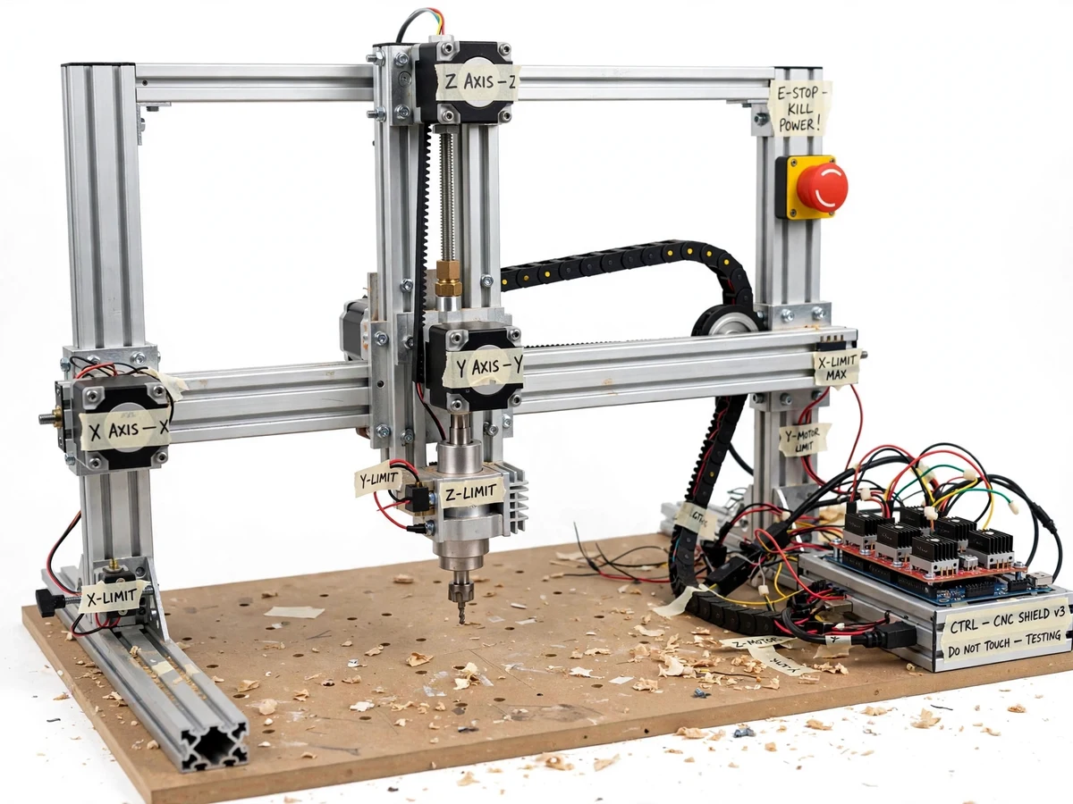
Students in mechanical and manufacturing programs study CNC machining in theory but rarely run a machine of their own: industrial CNC mills and routers are expensive, shop time is rationed, and most labs offer only supervised demonstrations. This keeps G-code, toolpath generation and motion control abstract — exactly the skills manufacturing employers and project reviewers expect a mechanical engineer to understand hands-on. A DIY 3-axis CNC router closes the gap: built from aluminium extrusion, NEMA 17 steppers, a trim-router spindle and an Arduino Uno running GRBL firmware, it executes the same CAD to CAM to G-code workflow as industrial machines at a student-friendly cost, inside a 500x500 mm work envelope (design target). The build also teaches the honest trade-offs of DIY motion hardware — belt stretch, backlash and frame flex set the accuracy ceiling — which is why this project documents calibration and repeatability honestly instead of claiming industrial precision.
The part is drawn in Fusion 360 or FreeCAD, and CAM writes a G-code file with feeds, speeds and depth of cut.
Follow the working sequence
How it works
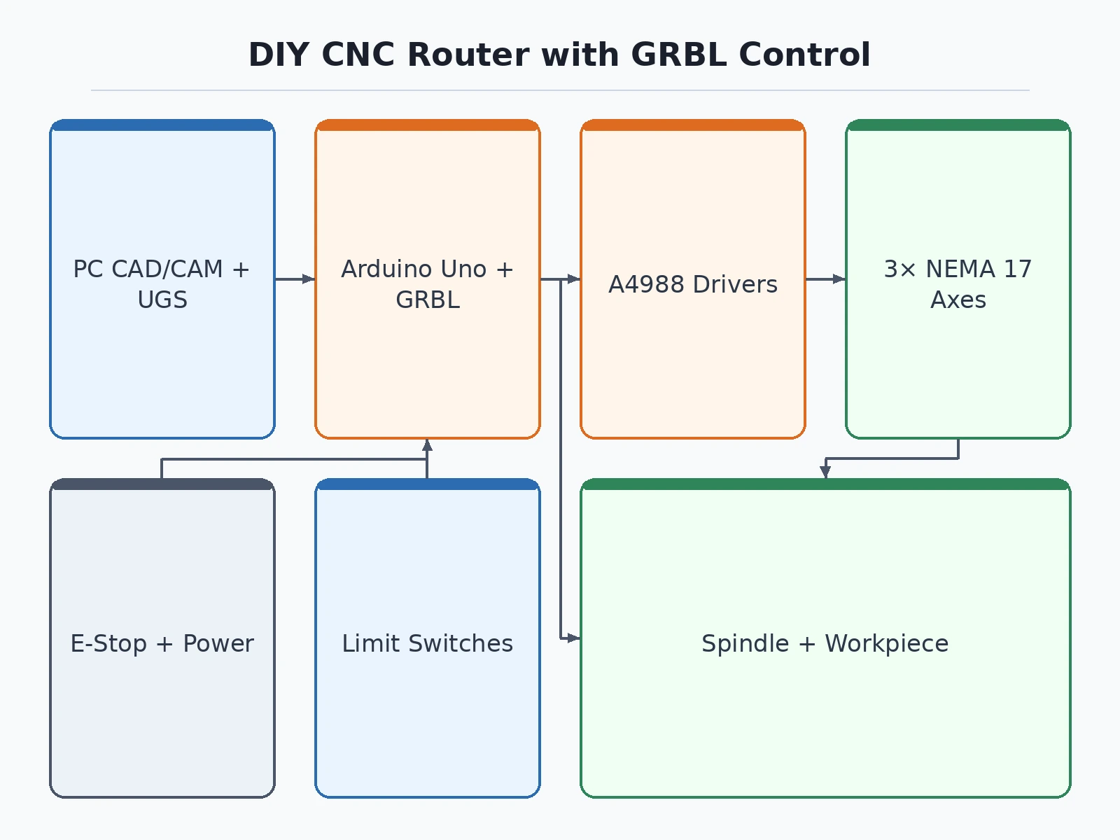
- The part is drawn in CAD software (Fusion 360 or FreeCAD) and the solid model is exported for toolpath generation.
- CAM software converts the model into machining operations — facing, pocketing, profiling — and writes a G-code file with feeds, speeds and depth of cut.
- A free G-code sender (Universal Gcode Sender or Candle) streams the file over USB to the Arduino Uno running GRBL 1.1h.
- GRBL parses each block, plans accelerations with 16-motion look-ahead, and generates step and direction pulses at up to 30 kHz (firmware capability).
- The A4988 or DRV8825 drivers translate the pulses into microstepped phase currents; the NEMA 17 motors turn belts and the lead screw to move the gantry in coordinated X-Y-Z motion.
- The trim-router spindle removes material along the toolpath while limit switches guard axis travel; the homing cycle before each session restores a repeatable machine zero.
- The finished part is measured with a vernier caliper and steps/mm values are fine-tuned in GRBL, closing the calibration loop before the next cut.
Tech stack:
- GRBL 1.1h firmware
- Arduino Uno (ATmega328P)
- CNC shield v3
- A4988 · DRV8825 stepper drivers
- NEMA 17 stepper motors
- GT2 timing belt · T8 lead screw
- Universal Gcode Sender · Candle
- Fusion 360 · FreeCAD (CAD-CAM)
| Parameter | Value |
|---|---|
| Controller | Arduino Uno (ATmega328P, 16 MHz) |
| Firmware | GRBL 1.1h (latest stable release) |
| Stepper motors | 3 x NEMA 17 bipolar, 1.8 deg step, 40 N.cm holding torque, 1.7 A/phase (datasheet values) |
| Drivers | A4988 (8-35 V, up to 2 A per coil with sufficient cooling — datasheet) or DRV8825 (8.2-45 V, up to 2.5 A — datasheet) |
| Microstepping | 1/8 or 1/16 (configurable) |
| X/Y drive | GT2 belt, 2 mm pitch, 20-tooth pulleys |
| Z drive | 8 mm T8 lead screw, 8 mm lead |
| Work area | 500 x 500 mm (design target) |
| Axis travel | X approx. 500 mm, Y approx. 500 mm, Z approx. 80 mm (design targets) |
| Theoretical resolution | 0.025 mm per microstep at 1/8 stepping (calculated from belt geometry) |
| Positioning repeatability | Design target approx. ±0.1 mm; verified by buyer-run dial-gauge procedure |
| Spindle | Trim-router class, approx. 500-800 W, manual speed control (configurable) |
| Materials | Wood, acrylic, MDF, plastics, PCB stock (soft materials only) |
| Homing | Mechanical limit switches on all 3 axes |
| Safety | Latching emergency-stop button, safe-start checklist |
| Power | 24 V DC supply for steppers (expected); Arduino via USB |
| Machine footprint | Approx. 750 x 750 mm (expected, including frame overhang) |
| Machine weight | Approx. 12-15 kg (expected, configuration-dependent) |
Project features
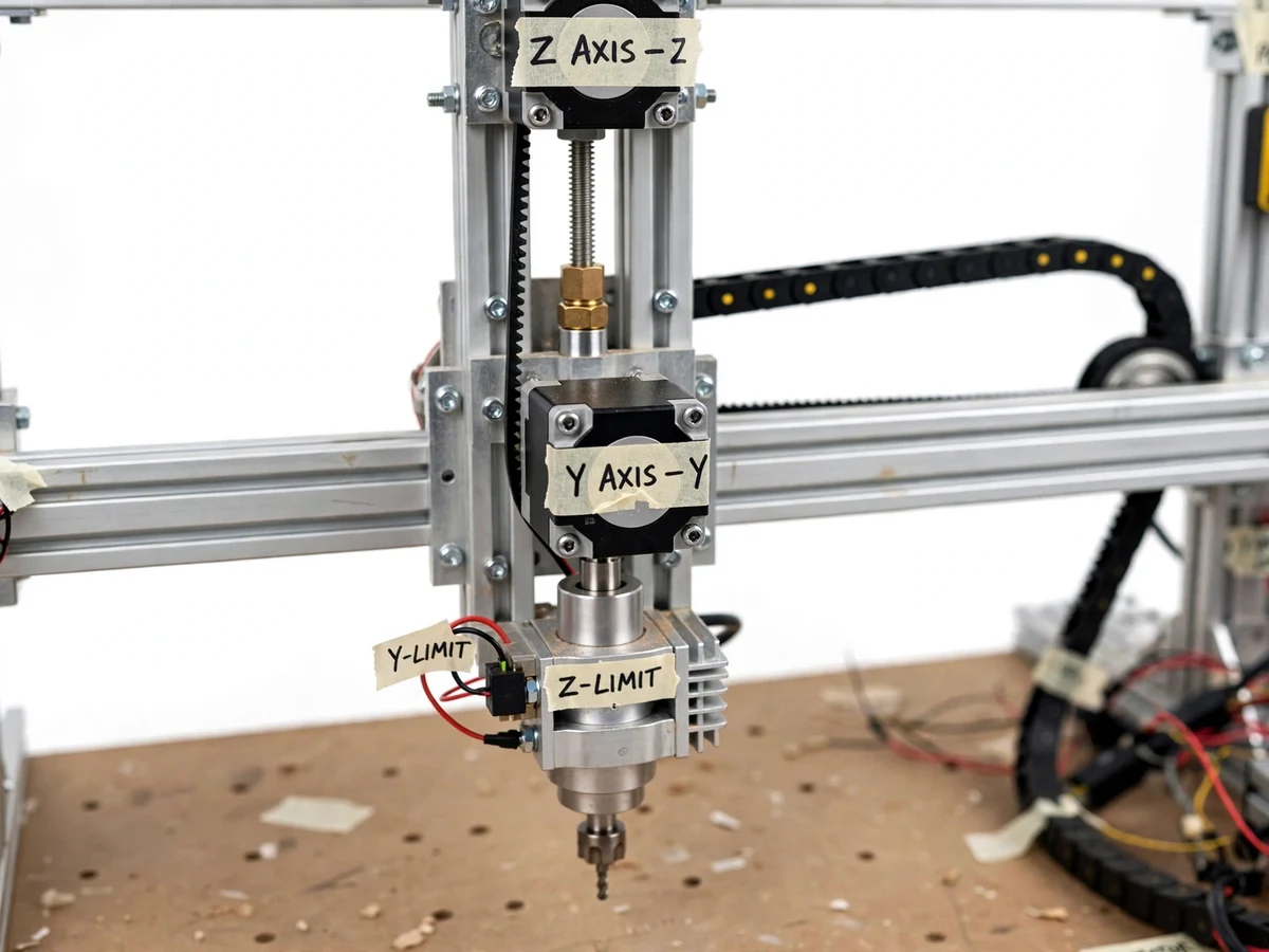
- [500 x 500 mm work area] The gantry and frame are sized for a 500 x 500 mm cutting envelope (design target) — enough for wooden models, acrylic display parts, plastic brackets and PCB panels in a single setup.
- [GRBL 1.1h motion control on Arduino Uno] An Arduino Uno runs GRBL 1.1h firmware on a CNC shield v3, accepting standards-compliant G-code with acceleration planning and 16-motion look-ahead for smooth coordinated movement.
- [Three NEMA 17 stepper axes with microstepping drivers] Each axis uses a NEMA 17 bipolar stepper (40 N.cm holding torque, 1.7 A per phase — datasheet values) driven by A4988 or DRV8825 modules at configurable 1/8 or 1/16 microstepping.
- [Belt-driven X and Y, lead-screw Z] X and Y axes run on GT2 timing belts (2 mm pitch, 20-tooth pulleys) for fast traverse; the Z axis uses an 8 mm T8 lead screw for the thrust needed in plunge moves.
- [Limit switches and repeatable homing] Mechanical limit switches on every axis guard against over-travel and provide a repeatable machine zero through the GRBL homing cycle at the start of every session.
- [Trim-router spindle with collet] A trim-router class spindle (approximately 500-800 W class, speed set manually) with a collet holds standard 3.175 mm and 6.35 mm shank end mills and engraving bits.
- [Emergency stop safety circuit] A wired latching emergency-stop button cuts spindle and motion power independently of software, and is part of the documented safe-start checklist shipped with the machine.
- [Configurable feeds, speeds and steps-per-mm] GRBL $$ settings — steps/mm per axis, acceleration, max feed rate and spindle mapping — are calibrated during the build and left adjustable, so the student can retune for different materials.
What is included
- Fully assembled 3-axis CNC router prototype with 500x500 mm work area (design target)
- Arduino Uno flashed with GRBL 1.1h and CNC shield with stepper drivers
- Trim-router spindle with collet set and starter end-mill bits
- Limit switches wired on all axes with emergency-stop button
- Wiring diagram and GRBL $$ settings reference sheet
- Axis calibration procedure with dial-gauge verification steps
- Project report PDF (background, design calculations, methodology, calibration results)
- PPT presentation for final review
- Viva Q&A preparation document (G-code, GRBL, stepper theory, calibration, safety)
Limitations & prerequisites
- Soft materials only (wood, acrylic, MDF, plastics, PCB stock) — steel and thick aluminium plate are out of scope because belt drives and the trim-router spindle cannot handle metal-cutting loads.
- Positioning repeatability is a design target of approx. ±0.1 mm, not an industrial guarantee; belt stretch, backlash and aluminium-frame flex set the accuracy ceiling on a DIY build.
- The frame and drivers are sized for hobby loads: deep cuts in hardwood need multiple shallow passes, or the tool will chatter and deflect.
- Eye protection is mandatory whenever the spindle runs; all cutting is done under supervision with a documented safe-start checklist, and dust extraction or a dust mask is recommended.
- The machine is an academic prototype, not an industrial CNC — it carries no CE/industrial certification and must not be used for commercial production.
- Driver current must be set with a multimeter (Vref procedure) during build; mis-set current overheats drivers or stalls motors — the procedure is documented in the wiring guide.
Frequently Asked Questions
Is this project suitable for a final-year project?
Yes. It suits mechanical, mechatronics and manufacturing programs, and also electronics or robotics students who want motion-control depth. It demonstrates CAD to CAM to G-code workflow, stepper-motor sizing, microstepping drivers, lead-screw and belt mechanics, machine calibration, and safety practice — a strong story for reviews and viva discussions.
Which controller and firmware run the machine?
The machine runs on an Arduino Uno with GRBL 1.1h firmware and a CNC shield v3 carrying A4988 or DRV8825 stepper drivers. A computer streams G-code over USB using a free sender such as Universal Gcode Sender or Candle. The GRBL settings file is documented so the student can explain every calibration parameter.
What materials can it cut — can it machine steel?
Wood, acrylic, MDF, plastics and PCB stock are the realistic materials. It is not built for steel or aluminium plate: the trim-router spindle, belt drives and aluminium extrusion frame flex under metal-cutting loads. Trying hard metals would break tools and ruin accuracy, so the scope is stated honestly as soft materials only.
How accurate is the finished machine?
The design target is approximately plus or minus 0.1 mm repeatability on small parts, verified with a buyer-run dial-gauge procedure. Belt stretch, backlash and frame flex keep it below industrial accuracy, and these limits are documented rather than hidden. Calibration of steps per millimetre per axis is part of the delivery.
What does the student need to run it safely?
Eye protection is mandatory whenever the spindle runs, with supervision during all cutting and dust extraction or a mask recommended. The machine ships with a wired emergency stop, limit switches and a documented safe-start checklist, so the student can demonstrate it confidently and safely in the lab.
Components & software requirements
- GRBL 1.1h firmware
- Arduino Uno (ATmega328P)
- CNC shield v3
- A4988 · DRV8825 stepper drivers
- NEMA 17 stepper motors
- GT2 timing belt · T8 lead screw
- Universal Gcode Sender · Candle
- Fusion 360 · FreeCAD (CAD-CAM)
Delivery information
Built-to-order project. Delivery timeline is shared after order confirmation based on current queue.
Support terms
Complete documentation, setup guide, and viva preparation included. Support for setup and explanation provided.
Download free synopsis (PDF)
Enter your name and email — the synopsis PDF downloads immediately. We may send occasional project updates; no spam, unsubscribe anytime.