
More project photos (2)
The problem
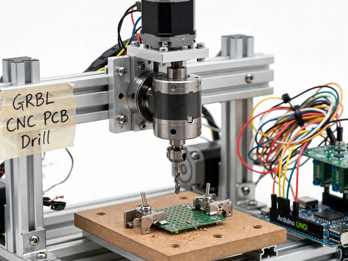
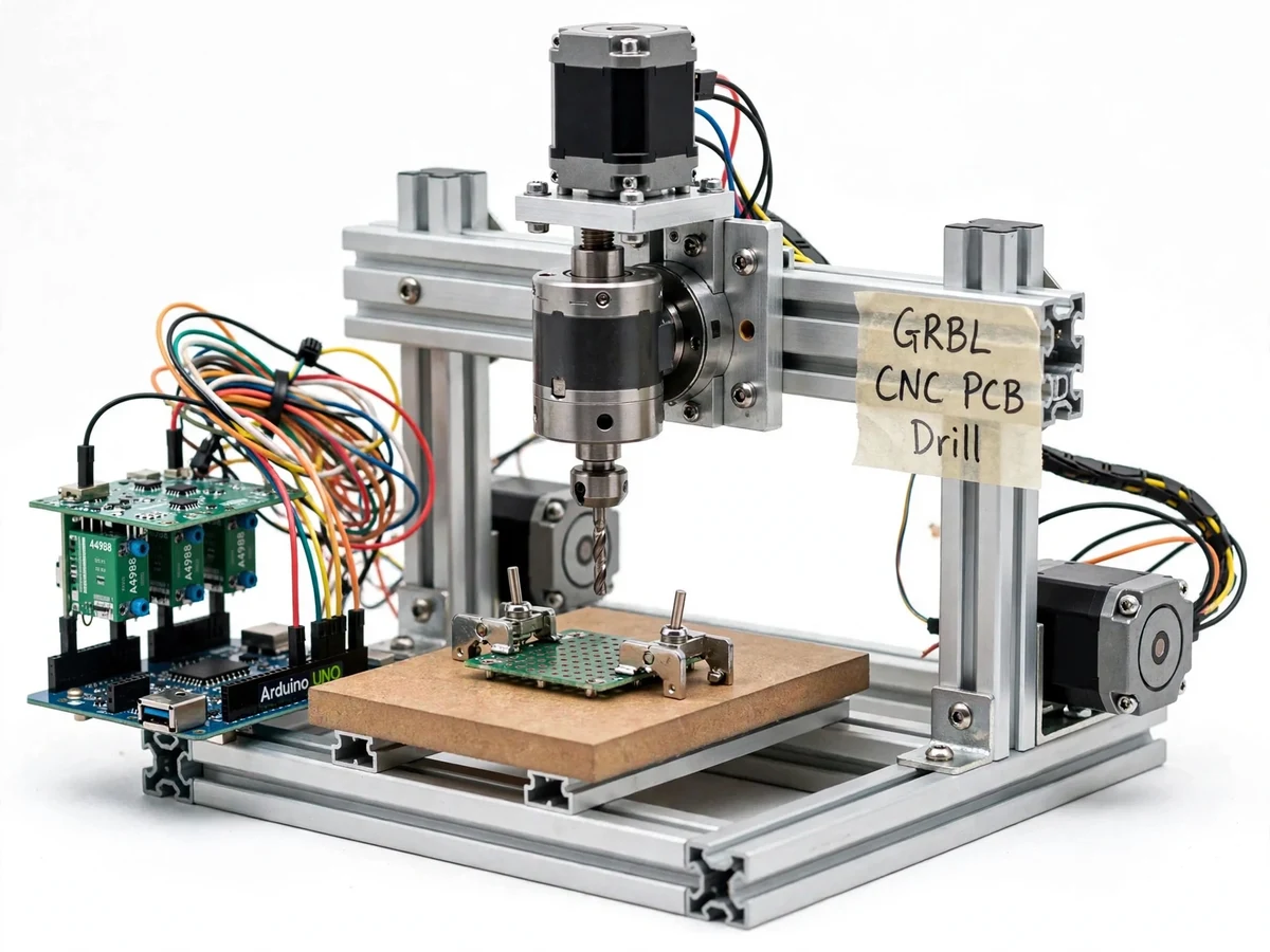
Prototype PCBs are stuck between two bad options: chemical etching is messy, imprecise for fine holes and unpleasant in a college lab, while ordering fabricated boards takes days and adds cost to every design iteration. A small CNC drilling machine closes that loop — it reads the same Gerber and Excellon drill data a fab house uses and drills the through-holes on a copper-clad board in the lab. This project is that machine plus the workflow: a 2020-aluminum-extrusion gantry with three NEMA 17 steppers, an Arduino Uno + CNC shield running GRBL v1.1 for real-time G-code interpretation, and a DC spindle with an ER11 collet holding tungsten-carbide bits. Students learn feed, speed and peck drilling on real FR4, set work coordinates, home the machine, and understand how acceleration planning turns G-code into smooth motion. The documented KiCad-to-FlatCAM chain takes a student from schematic to a drilled board in one sitting.
How it works
- The PCB is designed in KiCad (or Eagle) and Gerber plus Excellon drill files are exported.
- The drill file is loaded into FlatCAM, where tool diameter, feed rate and peck depth are set and drill G-code is generated.
- The copper-clad board is clamped on the spoil bed and all axes are homed with the GRBL homing cycle.
- Work zero is set at the board corner (G92/G10) using the jog controls in the G-code sender.
- The G-code streams over USB; GRBL plans acceleration and pulses the steppers through the A4988 drivers.
- The spindle spins the carbide bit while the Z axis pecks each hole to depth, retracting to clear FR4 dust.
- Holes are inspected; for double-sided boards the work zero is re-established and the second side is drilled.
Tech stack:
- Arduino Uno + CNC Shield V3 running GRBL v1.1 firmware
- NEMA 17 stepper motors with A4988 drivers (1/16 microstepping)
- 775 DC spindle motor with ER11 collet
- 2020 aluminum-extrusion frame, 8 mm linear rods with LM8UU bearings
- FlatCAM for drill G-code generation; Universal Gcode Sender for streaming
- 24 V DC power supply; mechanical endstops on all axes
| Parameter | Value |
|---|---|
| Controller | Arduino Uno + CNC Shield V3, GRBL v1.1 |
| Motors | 3x NEMA 17 (1.7 A/phase class) |
| Stepper drivers | A4988 at 1/16 microstepping |
| Spindle | 775 DC motor, 12–24 V, ER11 collet (0.6–3.175 mm bits) |
| Work area | ~200 x 150 x 60 mm (design target, build-dependent) |
| Positioning repeatability | Design target ±0.1 mm, verified with motion tests during the build |
| Frame | 2020 aluminum extrusion with 8 mm linear rods |
| Drill bits | Tungsten carbide, 0.6–1.2 mm for PCB through-holes |
| Homing | Mechanical endstops on X, Y and Z |
| Interface | USB serial G-code streaming at 115200 baud |
| Power | 24 V DC for steppers/spindle; 5 V logic via Arduino |
Project features
- GRBL Motion Control: an Arduino Uno + CNC Shield V3 runs GRBL v1.1, interpreting G-code in real time with trapezoidal acceleration planning.
- 3-Axis Gantry: X/Y gantry on 2020 aluminum extrusion with linear rods and bearings; Z axis on a lead screw for controlled plunge depth.
- NEMA 17 Stepper Drive: three 1.7 A-class steppers on A4988 drivers at 1/16 microstepping for smooth, quiet motion.
- ER11 Spindle: a DC spindle motor with an ER11 collet chuck holds 0.6–3.175 mm tungsten-carbide drill bits with low runout.
- Homing and Limit Switches: mechanical endstops on all three axes; the GRBL homing cycle establishes a repeatable machine zero.
- G-Code Workflow: a documented KiCad → Gerber → FlatCAM → G-code-sender chain; drill files stream to the machine over USB.
- PCB Clamping Bed: a sacrificial MDF spoil board with clamps holds single- and double-sided copper-clad boards flat during drilling.
- Emergency Stop: a panel E-stop cuts spindle and stepper power independently of the firmware.
What is included
- Assembled and motion-tested 3-axis PCB drilling machine
- GRBL firmware pre-flashed with the machine configuration ($ settings documented)
- Wiring diagram, mechanical assembly drawings and full bill of materials
- FlatCAM drill-G-code workflow guide with screenshots
- Sample drill files and a test PCB layout for the first run
- Project report PDF, PPT presentation and viva Q&A document
Limitations & prerequisites
- Positioning repeatability is a design target (±0.1 mm) checked with dial-indicator motion tests during your build — it is not a certified machine-tool specification.
- This is a drilling machine: it drills through-holes. Trace isolation milling with a V-bit is possible but slower, and is treated as an optional extension rather than the base claim.
- FR4 dust is abrasive and unhealthy to breathe — drilling needs ventilation or dust extraction plus eye protection; the safety guide covers this.
- Carbide bits are brittle and snap under side loads; the workflow guide uses conservative feeds, and breaking a bit while learning is normal — spares are listed in the BOM.
- Feed and speed must suit the bit diameter; aggressive settings stall the 775 spindle — the guide gives starting values per bit size.
- G-code streams over USB from a PC, so long jobs need a stable connection and should not run unattended.
Frequently Asked Questions
Is this project suitable for a final-year project?
Yes — for Mechanical, Mechatronics and Electronics programs. It covers machine design, stepper-motor control, G-code, GRBL firmware configuration and the CAD-to-part workflow, with viva material on microstepping versus torque, acceleration planning and why peck drilling suits FR4.
Which firmware and controller are used?
GRBL v1.1 on an Arduino Uno with a CNC Shield V3; all configuration is done through documented GRBL $ parameters.
Can it mill PCB traces as well?
The base build is a drilling machine. V-bit isolation milling works as an optional extension with slower feeds and lighter cuts.
What software do I need?
KiCad (free) for PCB design, FlatCAM (free) for drill G-code generation, and Universal Gcode Sender (free) for streaming — the full chain is documented step by step.
What will I receive with the project?
The assembled machine, flashed firmware with documented settings, wiring and assembly drawings, BOM, the FlatCAM workflow guide, sample files, report, PPT and viva Q&A. Suitable for B.E./B.Tech final-year projects in Mechanical, Mechatronics and Electronics Engineering.
Components & software requirements
- Arduino Uno + CNC Shield V3 running GRBL v1.1 firmware
- NEMA 17 stepper motors with A4988 drivers (1/16 microstepping)
- 775 DC spindle motor with ER11 collet
- 2020 aluminum-extrusion frame, 8 mm linear rods with LM8UU bearings
- FlatCAM for drill G-code generation; Universal Gcode Sender for streaming
- 24 V DC power supply; mechanical endstops on all axes
Delivery information
Built-to-order project. Delivery timeline is shared after order confirmation based on current queue.
Support terms
Complete documentation, setup guide, and viva preparation included. Support for setup and explanation provided.