
More project photos (2)
The problem
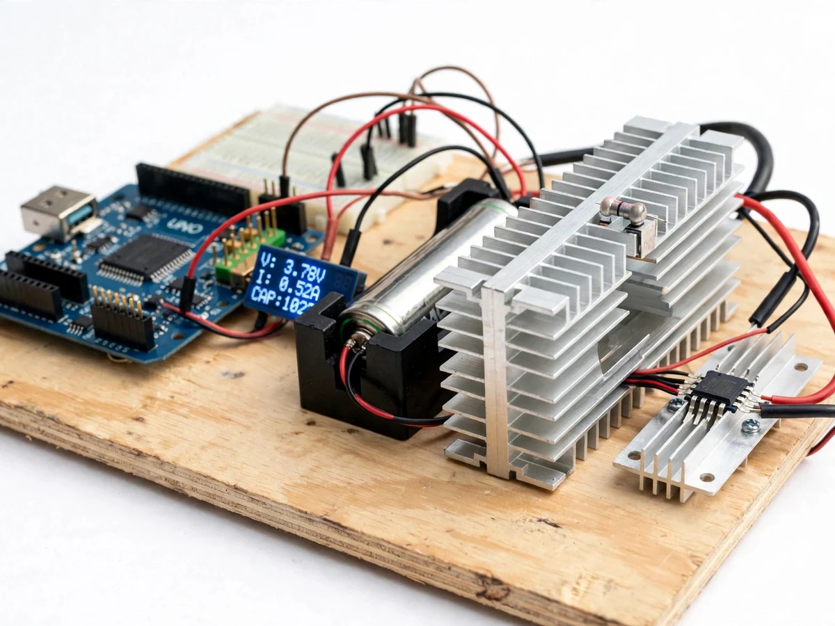
The DIY battery capacity tester is an Arduino-based instrument that measures how much charge a rechargeable cell actually delivers, instead of trusting the capacity printed on its label. Many students and hobbyists own 18650 lithium-ion cells whose printed ratings are optimistic, reused, or simply unknown, so a cell that should run a project for hours can die far sooner than expected. This tester discharges one cell at a time through a controlled load, logs voltage and current throughout the discharge, and stops at a safe cutoff voltage. The result is a measured capacity figure in milliamp-hours plus an internal resistance estimate, both of which say far more about a cell's real condition than its label does. Because the build uses an Arduino Uno, a MOSFET-switched load, a shunt resistor and an OLED display, it also teaches measurement, power handling and firmware timing in one compact bench instrument.
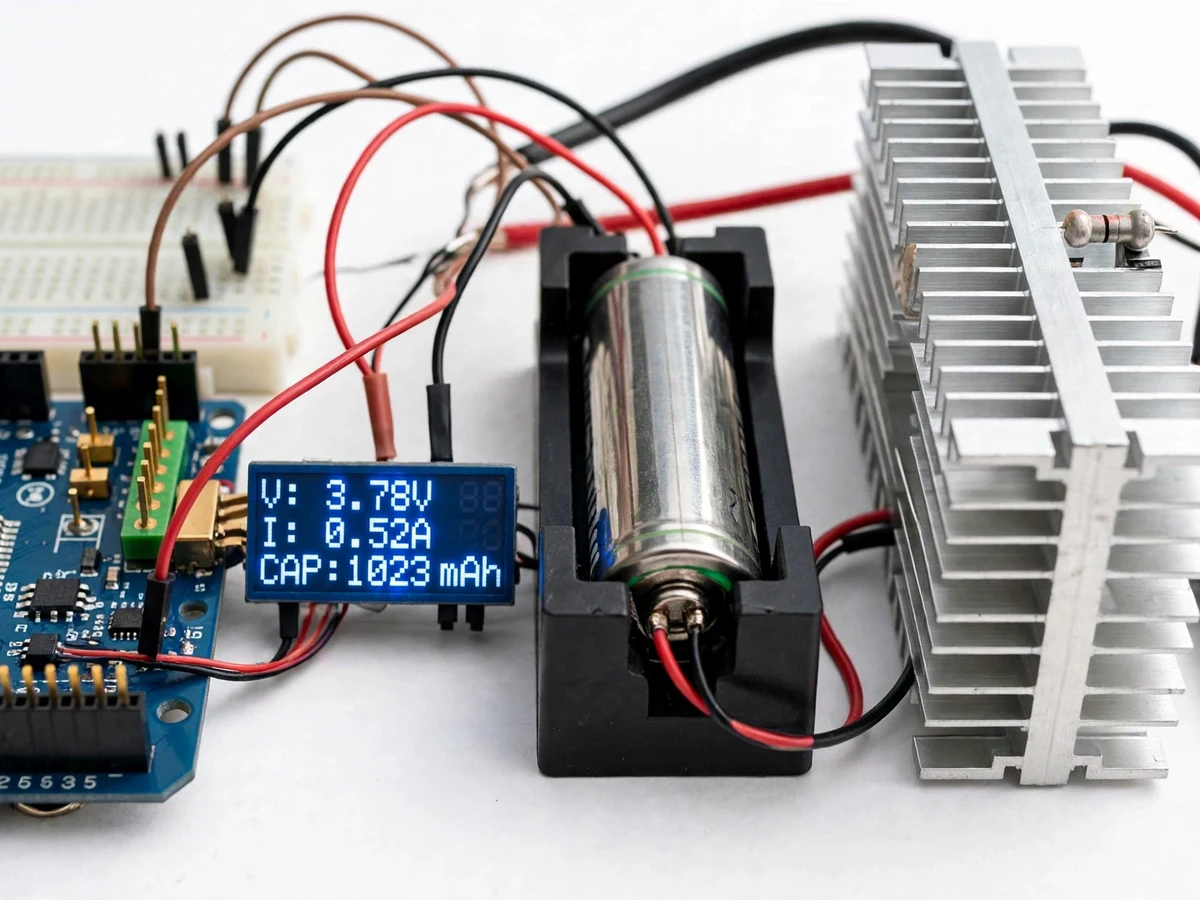
The cell under test, placed in its holder.
Follow the working sequence
How it works
The tester works by discharging the cell under test in a controlled way and measuring what comes out of it from start to finish. The cell is placed in its holder and its open-circuit voltage is recorded before any load is connected. The Arduino then switches on the MOSFET load, current flows through the power resistor, and the firmware samples voltage and current repeatedly, accumulating charge over time. At the same time it compares the loaded voltage with the earlier open-circuit reading to estimate internal resistance. The OLED display shows live voltage, current, elapsed time and accumulated capacity throughout the run. When the cell voltage reaches the cutoff level, the Arduino switches the load off and holds the final capacity and resistance figures on screen for recording. No separate lab instrument is needed for the core result, because the same Arduino that switches the load also performs the measurement and drives the display.
- The charged cell is placed in the holder and the Arduino records its open-circuit voltage with no load connected.
- The firmware switches the MOSFET on, connecting the power-resistor load, and discharge current begins to flow.
- The Arduino repeatedly samples cell voltage and the voltage across the shunt resistor, averaging several readings to reduce noise.
- Discharge current is computed from the shunt voltage, and the firmware integrates current over time to accumulate delivered capacity.
- Internal resistance is derived from the drop between the open-circuit voltage and the loaded voltage, divided by the measured load current.
- When the cell voltage reaches the cutoff voltage, the firmware switches the MOSFET off and holds the final capacity and resistance on the display.
Tech stack:
- Arduino Uno (ATmega328P)
- Arduino IDE firmware in C/C++
- MOSFET-switched power-resistor discharge load
- Shunt-resistor current sensing
- 0.96-inch OLED display over I2C
- 18650 lithium-ion cell holder
- Breadboard and plywood prototype base
| Parameter | Value |
|---|---|
| Controller | Arduino Uno with ATmega328P microcontroller (datasheet value) |
| ADC resolution | 10-bit (datasheet value), counts 0–1023 |
| ADC accuracy | ±2 LSB absolute accuracy (datasheet value) |
| Display | 0.96-inch OLED display over I2C (design target size) |
| Cell under test | One 18650 lithium-ion cell at a time (design target) |
| Discharge load | MOSFET-switched power resistor on a heatsink (design target) |
| Discharge current | Approximately 0.5 A (design target) |
| Current sensing | Shunt resistor of 0.1 ohm (design target) with ADC sampling |
| Samples per reading | 16 samples averaged per reading (design target) |
| Cutoff voltage | 3.0 V per cell (design target, lithium-ion only) |
| Capacity output | Delivered charge in milliamp-hours, integrated over the run |
| Internal resistance output | Voltage drop divided by load current, in milliohms (derived value) |
| Power supply | 5 V USB supply for the Arduino and display (design target) |
Project features
The tester is built around four capabilities that work together during every discharge run. First, it performs a controlled discharge, switching the load on and off through a MOSFET while the Arduino tracks voltage and current. Second, it integrates discharge current over time to report delivered capacity in milliamp-hours, updating the figure live on the OLED display. Third, it estimates internal resistance from the voltage drop between the unloaded cell and the same cell under a known load current, a first-principles measurement rather than a guessed health percentage. Fourth, it protects the cell under test by stopping the discharge automatically at a safe cutoff voltage, so a forgotten test cannot over-discharge a lithium-ion cell. Together these give a student a repeatable bench procedure: charge the cell, run the tester, and record capacity and resistance for comparison.
- [Controlled MOSFET discharge] The Arduino switches the discharge load through a MOSFET, so each test starts and stops cleanly under firmware control instead of relying on a manually connected resistor. (Implemented)
- [Live OLED readout] Voltage, discharge current, elapsed time and accumulated capacity are shown live on a small OLED display throughout the run, with final figures held on screen when the test ends. (Implemented)
- [Capacity measurement in milliamp-hours] The firmware samples current at regular intervals and integrates it over time, so the reported capacity is the charge the cell actually delivered during that discharge. (Implemented)
- [Internal resistance estimation] The tester records the cell voltage before loading and again under a known load current, then derives resistance from the voltage drop divided by the load current. (Implemented)
- [Automatic cutoff protection] When the cell voltage reaches the configured cutoff, the firmware switches the load off automatically, so an unattended test cannot over-discharge the cell. (Implemented)
- [Adjustable cutoff and discharge current] The cutoff voltage and the discharge current are set as firmware constants, so they can be retuned for a different cell type or a gentler test without rewiring the prototype. (Configurable)
- [Serial logging and extra cell holders] A serial output of the test readings and holders for other cell sizes can be added on request, for students who want to plot discharge curves or test more than one cell format. (Optional customization, not in the base build)
What is included
- Working battery capacity tester prototype (Arduino, MOSFET load, shunt sensing, OLED display, cell holder)
- Arduino firmware source code with commented measurement and cutoff logic
- Circuit and wiring documentation for the discharge load and sense connections
- Component list with the controller, MOSFET, resistor, shunt and display used
- Step-by-step test procedure: charging, running a discharge, and recording capacity and resistance
- Project abstract PDF (10-section structure matching this page)
- Demonstration guidance for presenting a live discharge run
Limitations & prerequisites
- The base build tests one cell at a time; it is not a multi-cell charger or a pack balancer.
- Internal resistance here is an estimate derived from a single loaded-voltage reading, so it is approximate and varies with temperature, state of charge and load current.
- Capacity results depend on the discharge current and cutoff used, so figures from different settings are not directly comparable.
- The tester only discharges; it does not charge cells, and a separate charger is needed before each test.
- The 3.0 V cutoff is a design target for lithium-ion cells only; other chemistries need different cutoff values set in firmware.
- The discharge load turns cell energy into heat, so the resistor and MOSFET need their heatsink and airflow, and the prototype must not be left running inside a closed box.
- Damaged, swollen, leaking or physically abused cells must never be tested; this is a bench instrument for healthy cells in good condition.
- Measurement resolution is bounded by the 10-bit ADC and its ±2 LSB absolute accuracy (datasheet values), so small voltage differences carry visible rounding.
Frequently Asked Questions
Is this project suitable for a final-year project?
Yes, it fits Electronics and Telecommunication final-year work well, because it combines embedded firmware, analog measurement, power electronics and a repeatable test procedure in one demonstrable instrument. It gives a student real readings to present and discuss, rather than a simulation alone, and the measurement method itself is straightforward to explain and defend.
How is internal resistance actually measured?
Internal resistance is derived from first principles: the tester records the cell voltage with no load, then again under a known load current, and divides the voltage drop by that current. This is a genuine electrical measurement, not a guessed health percentage, but it is an estimate that shifts with temperature, charge level and load current.
Which cells can the tester check?
The base build is designed for one 18650 lithium-ion cell at a time, which is the most common rechargeable cell in student projects. Holders for other cell sizes and cutoff settings for other chemistries are possible as optional customizations, but they are not part of the base build and need firmware changes.
Does the tester also charge the cell?
No, this tester only discharges and measures; it cannot charge a cell. The cell must be fully charged with a separate charger before each test, and the discharge run then measures what the charged cell actually delivers down to the cutoff voltage.
Can the discharge current or cutoff voltage be changed?
Yes, both are firmware constants, so a student can retune them for a gentler test or a different cell type without rewiring anything. Any change must stay within safe limits for the cell and the heatsink, and lithium-ion cells must never be discharged below their safe cutoff voltage.
What do I receive with the project?
You receive the working prototype with its Arduino firmware, circuit and wiring documentation, a component list, and a step-by-step test procedure for running a discharge and recording capacity and resistance. A matching 10-section abstract PDF and demonstration guidance for presenting a live test run are also included.
Components & software requirements
- Arduino Uno (ATmega328P)
- Arduino IDE firmware in C/C++
- MOSFET-switched power-resistor discharge load
- Shunt-resistor current sensing
- 0.96-inch OLED display over I2C
- 18650 lithium-ion cell holder
- Breadboard and plywood prototype base
Delivery information
Built-to-order project. Delivery timeline is shared after order confirmation based on current queue.
Support terms
Complete documentation, setup guide, and viva preparation included. Support for setup and explanation provided.
Download free synopsis (PDF)
Enter your name and WhatsApp number — the synopsis PDF downloads immediately. We may send occasional project updates on WhatsApp; no spam.