
More project photos (3)
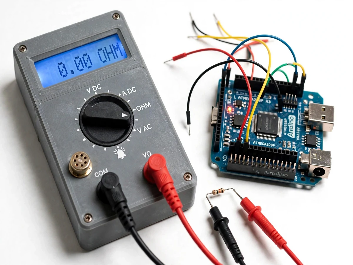
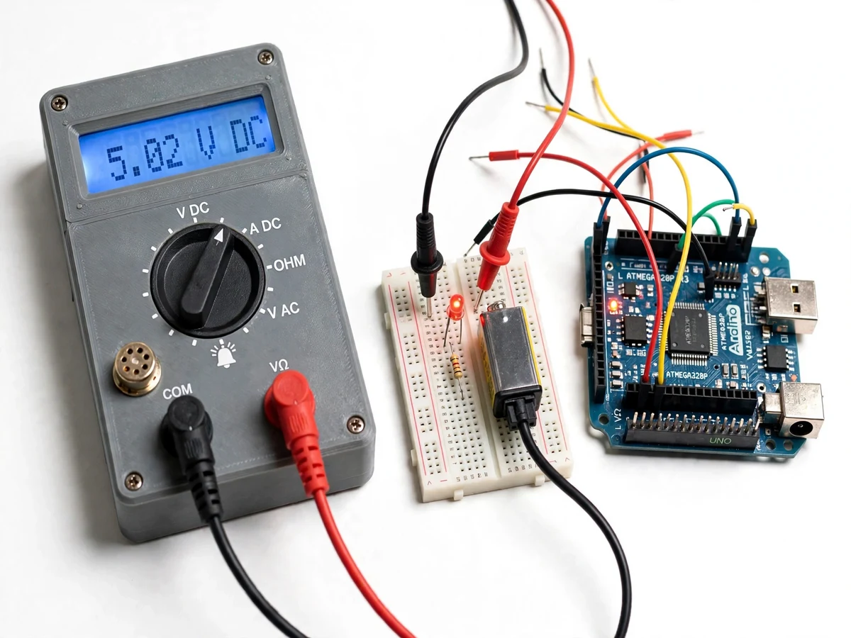
The problem
A digital multimeter is the first instrument an electronics student reaches for: one handheld tool that measures voltage, current, resistance and continuity, so a circuit can be checked without a bench full of separate meters. This project builds that instrument from scratch as a probe-based bench prototype around an Arduino board with an ATmega328P microcontroller. Two test probes feed the circuit under test into a front-end of voltage dividers and a shunt resistor, the microcontroller converts the scaled signals with its 10-bit analogue-to-digital converter, and the result appears on a 16 × 2 LCD with the correct unit and mode. A rotary selector switch chooses between DC voltage, AC voltage, DC current, resistance, continuity and diode test, and auto-ranging picks the best measurement range automatically. The build is deliberately educational: every stage from divider ratio to ADC step size is visible in the firmware and the report, so the student can explain exactly how each number was produced.
Most students use a commercial meter as a black box: they read a number but cannot explain where it came from, why the range matters, or what the meter is doing to the circuit. This project closes that gap by making the measurement chain itself the subject — the divider, the shunt and the firmware that converts raw counts into a displayed value. The result is a working instrument and a complete explanation of how it works, which is exactly what a viva panel asks about.
The student connects the probes and turns the rotary selector.
Follow the working sequence
How it works
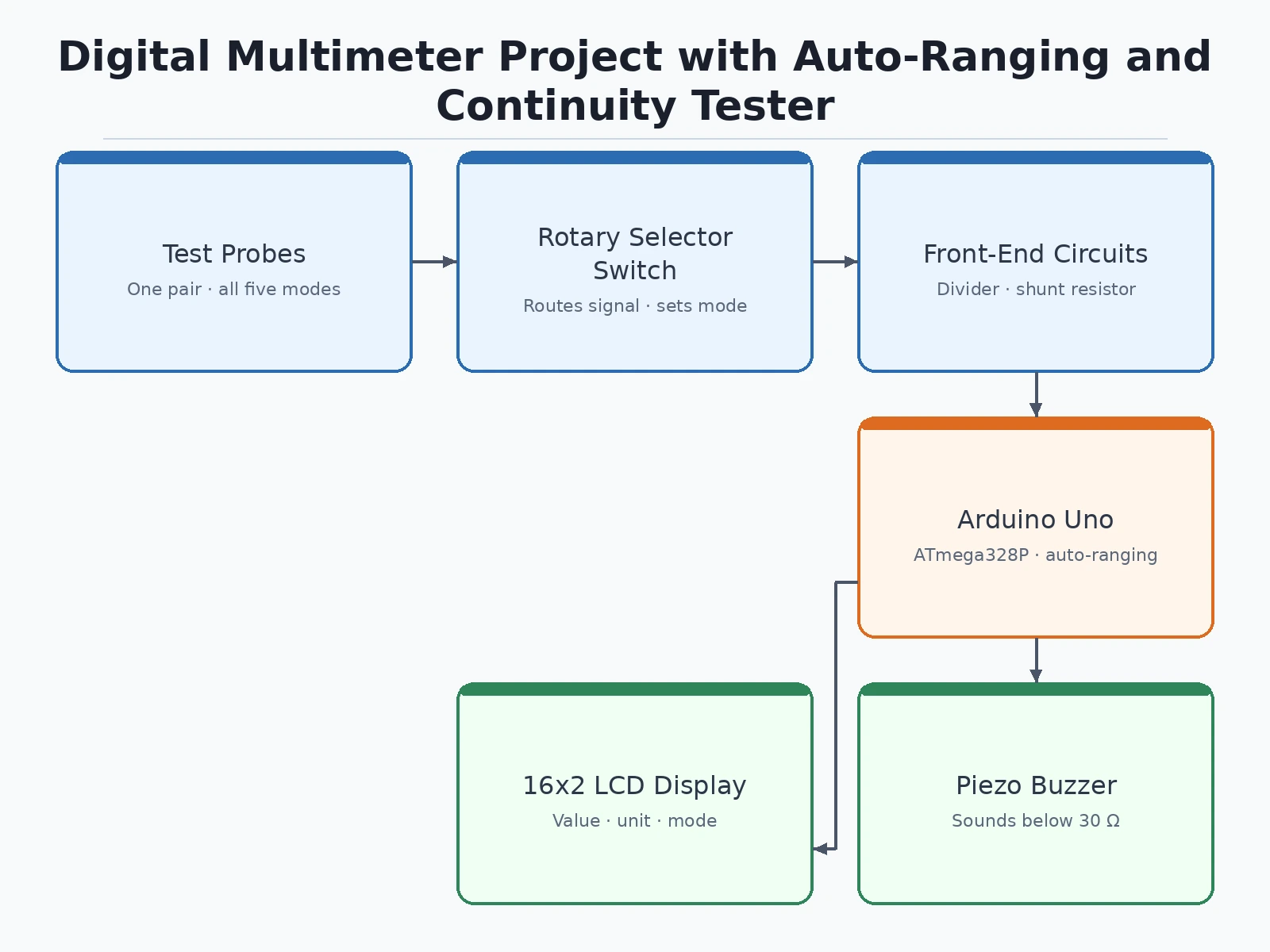
The measurement starts at the two test probes, which bring the circuit's signal into the meter's front-end. The rotary selector switch routes that signal to the right circuit: a voltage divider scales DC and AC voltages down to the 0–5 V range the microcontroller can accept, a shunt resistor turns DC current into a small proportional voltage, and a known reference resistor forms a divider with the unknown resistor. The ATmega328P reads the scaled voltage with its 10-bit analogue-to-digital converter, averages several samples to steady the reading, and the firmware converts the raw ADC count into a real value using the divider ratio or shunt value. Auto-ranging compares the reading against the range limits and moves to a finer or coarser range when the value sits near an edge. Finally the result is shown on the 16 × 2 LCD with its unit and mode, and in continuity mode the buzzer sounds when the resistance is below the threshold.
- The red and black test probes are connected across the component or circuit under test, and the rotary selector switch is turned to the required mode.
- The selector routes the probe signal to the correct front-end: a voltage divider for voltage modes, a shunt resistor for current mode, or a reference-resistor divider for resistance mode.
- The ATmega328P samples the scaled voltage with its 10-bit analogue-to-digital converter and averages several consecutive samples to steady the reading.
- The firmware converts the averaged ADC count into a real value using the divider ratio, shunt value or reference resistor for the active mode.
- Auto-ranging compares the value against the current range limits and shifts to a finer or coarser range so the display uses the most precise range available.
- The result appears on the 16 × 2 LCD with its unit and mode; in continuity mode the piezo buzzer sounds when the measured resistance is below the threshold.
Tech stack:
- Arduino Uno · ATmega328P
- Arduino IDE · C++
- 16 × 2 LCD display
- Voltage divider front end
- Shunt resistor current sensing
- Rotary selector switch
- Piezo buzzer continuity tester
- 9 V battery power
| Parameter | Value |
|---|---|
| Controller | ATmega328P on Arduino Uno (16 MHz clock, datasheet value) |
| ADC resolution | 10-bit (datasheet value), 1024 steps |
| ADC step size | 4.88 mV per step at 5 V reference (design calculation) |
| DC voltage range | 0–50 V (design target) |
| AC voltage range | 0–30 V AC (design target, low-voltage sources only) |
| DC current range | 0–500 mA (design target) |
| Resistance range | 0–100 kΩ (design target) |
| Continuity threshold | Below 30 Ω (design target) |
| Voltage divider ratio | 100 kΩ : 10 kΩ, scales 0–55 V to 0–5 V (design calculation) |
| Shunt resistor | 0.1 Ω, 1 W (design value) |
| Display | 16 × 2 character LCD |
| Display update rate | Approximately 2 readings per second (design target) |
| Power supply | 9 V battery |
| Input protection | Series resistor and clamping diodes (design value) |
Requirements
- Arduino Uno board with ATmega328P microcontroller
- 16 × 2 character LCD with I2C adapter
- Rotary selector switch (6-position)
- Red and black test probes with banana jacks
- Piezo buzzer
- 9 V battery with battery clip
- Resistors: 100 kΩ and 10 kΩ voltage divider, 0.1 Ω shunt resistor, reference resistor for resistance mode
- Breadboard or general-purpose PCB and connecting wires
- Plastic enclosure for the bench prototype
- Arduino IDE for firmware upload; no internet connection is needed to use the meter
Project features
The multimeter's strongest capabilities are its auto-ranging measurement, its five probe-based measurement modes, its continuity buzzer, and its clear LCD readout. Auto-ranging removes the most common beginner mistake — picking the wrong range — by letting the firmware select the range that gives the most useful reading. The five modes cover the measurements an electronics lab actually needs every day: DC voltage, AC voltage, DC current, resistance and continuity, all through the same pair of probes. The continuity buzzer turns a wiring check into a sound, so a student can test a connection without watching the display. The 16 × 2 LCD always shows the value together with its unit and mode, so a reading is never ambiguous. The rotary selector switch makes mode changes physical and obvious, so the meter behaves like a real handheld instrument rather than a software demo, and the over-range indication warns the user before a reading is trusted.
- [Auto-ranging measurement] (Implemented) The firmware samples the scaled input, compares it against range thresholds and switches the measurement range automatically, so the display uses the most precise range available without the user turning a dial.
- [Five measurement modes] (Implemented) One pair of probes measures DC voltage, AC voltage, DC current, resistance and continuity, selected with the rotary switch; the firmware applies the correct scaling and unit for each mode.
- [Continuity buzzer] (Implemented) In continuity mode the piezo buzzer sounds when the measured resistance falls below a 30 Ω threshold (design target), so wiring faults and broken connections can be found by ear.
- [Rotary selector switch] (Implemented) A physical rotary switch routes the probe signal to the correct front-end circuit and tells the firmware which mode is active, so the meter behaves like a real handheld instrument.
- [LCD readout with unit and mode] (Implemented) A 16 × 2 character LCD shows the measured value together with its unit and the active mode, with an over-range indication when the input exceeds the selected range.
- [Diode test] (Optional) A diode-check mode can be added on request: the meter applies a small test current and displays the forward voltage drop of the diode under test.
- [Low-battery indication] (Future scope) A battery-voltage monitor that warns when the 9 V battery is running low is listed as future scope and is not part of the base build.
What is included
- Working bench multimeter prototype in an enclosure with test probes
- Complete firmware source code (Arduino IDE, C++)
- Circuit diagram and wiring documentation
- Component list with values used in the build
- Setup and calibration instructions
- Project abstract PDF
- Project report (background, front-end design, firmware logic, test procedure, limitations)
- PPT presentation for final review
- Viva Q&A preparation document (ADC, divider, shunt, auto-ranging, safety limits)
- Demonstration guidance for the viva
Timeline
- Week 1: front-end design and component selection — divider ratios, shunt value and range plan, with the circuit diagram drawn and checked.
- Week 2: front-end build and firmware — voltage, current and resistance modes coded and tested one at a time on the bench.
- Week 3: integration and testing — auto-ranging, continuity buzzer and LCD readout combined, with readings checked against a reference meter on known sources.
- Week 4: documentation and demo — report, abstract, PPT and viva Q&A prepared, with a rehearsed demonstration of all five modes.
Support
- Build guidance and doubt-clearing during the project period, with the firmware and circuit explained step by step.
- Documentation support: report, abstract, PPT and Q&A are prepared to match the delivered build, and corrections are made if the college format needs a change.
- Customization on request: extra ranges, diode test mode or an OLED display can be added based on technical feasibility and timeline.
- Request a quotation on WhatsApp with your branch, college deadline and any required customization — the scope, price and delivery date are confirmed before the build starts.
Limitations & prerequisites
- This is a low-voltage educational prototype, not a certified CAT-rated commercial meter: it must never be used on mains distribution panels or any mains-voltage circuit.
- Readings are indicative, not calibration-grade: accuracy is limited by the 10-bit ADC (datasheet value) and by resistor tolerances in the divider and shunt.
- AC voltage is an averaged sine-wave estimate (design approach), not a true RMS measurement, and it is valid only for low-voltage AC sources.
- DC current is limited to a 0–500 mA range (design target); measuring higher currents needs a different shunt and is out of scope.
- Resistance must be measured with the circuit powered off: parallel paths in a live circuit will distort the reading.
- The 9 V battery voltage falls as it discharges, which can shift readings over a long session; the low-battery warning is future scope.
- The meter has no data logging or computer connectivity in the base build; readings are read from the LCD only.
Frequently Asked Questions
Is this project suitable for a final-year project?
Yes. This project fits final-year work in Electronics, E&TC and Electrical Engineering because it combines analogue front-end design, embedded firmware and measurement theory in one working instrument. The student can demonstrate divider and shunt calculations, ADC conversion and auto-ranging logic, and explain every number on the display, which is exactly the depth a viva panel looks for.
How does auto-ranging work?
Auto-ranging lets the firmware choose the measurement range instead of the user. The meter samples the scaled input, compares the value against the current range limits, and shifts to a finer range when the reading is small or a coarser range when it approaches the limit. The display then shows the most precise reading available, and an over-range indication appears if the input exceeds the highest range.
Can this meter measure mains voltage?
No. This is a low-voltage educational prototype with a 0–50 V DC and 0–30 V AC design-target range, and it must never be connected to mains supply or distribution panels. It has no CAT rating and no mains-grade isolation. It is built for batteries, lab power supplies and low-voltage transformer outputs only, which is where a student project belongs.
How accurate are the readings?
The readings are indicative rather than calibration-grade. The ATmega328P's 10-bit ADC gives 1024 steps, so one step is 4.88 mV at a 5 V reference (design calculation), and resistor tolerances in the divider and shunt add further error. The report documents the expected error honestly and shows how readings were checked against a reference meter on known sources.
How is this different from a clamp meter?
A clamp meter measures AC current only, without contact, by clamping around a live wire, and it cannot measure voltage or resistance. This multimeter is a probe-based contact instrument: its test probes touch the circuit and measure DC voltage, AC voltage, DC current, resistance and continuity. The two instruments solve different problems and use completely different front-ends.
Can extra modes or ranges be added?
Yes. A diode test mode, an extra voltage range, or an OLED display instead of the 16 × 2 LCD can be added on request. Each addition changes the front-end or the firmware, so the scope, price and delivery date are confirmed on WhatsApp before the build starts, and the report is updated to match the delivered version.
Components & software requirements
- Arduino Uno · ATmega328P
- Arduino IDE · C++
- 16 × 2 LCD display
- Voltage divider front end
- Shunt resistor current sensing
- Rotary selector switch
- Piezo buzzer continuity tester
- 9 V battery power
Delivery information
Built-to-order project. Delivery timeline is shared after order confirmation based on current queue.
Support terms
Complete documentation, setup guide, and viva preparation included. Support for setup and explanation provided.
Download free synopsis (PDF)
Enter your name and WhatsApp number — the synopsis PDF downloads immediately. We may send occasional project updates on WhatsApp; no spam.