
More project photos (2)
The problem
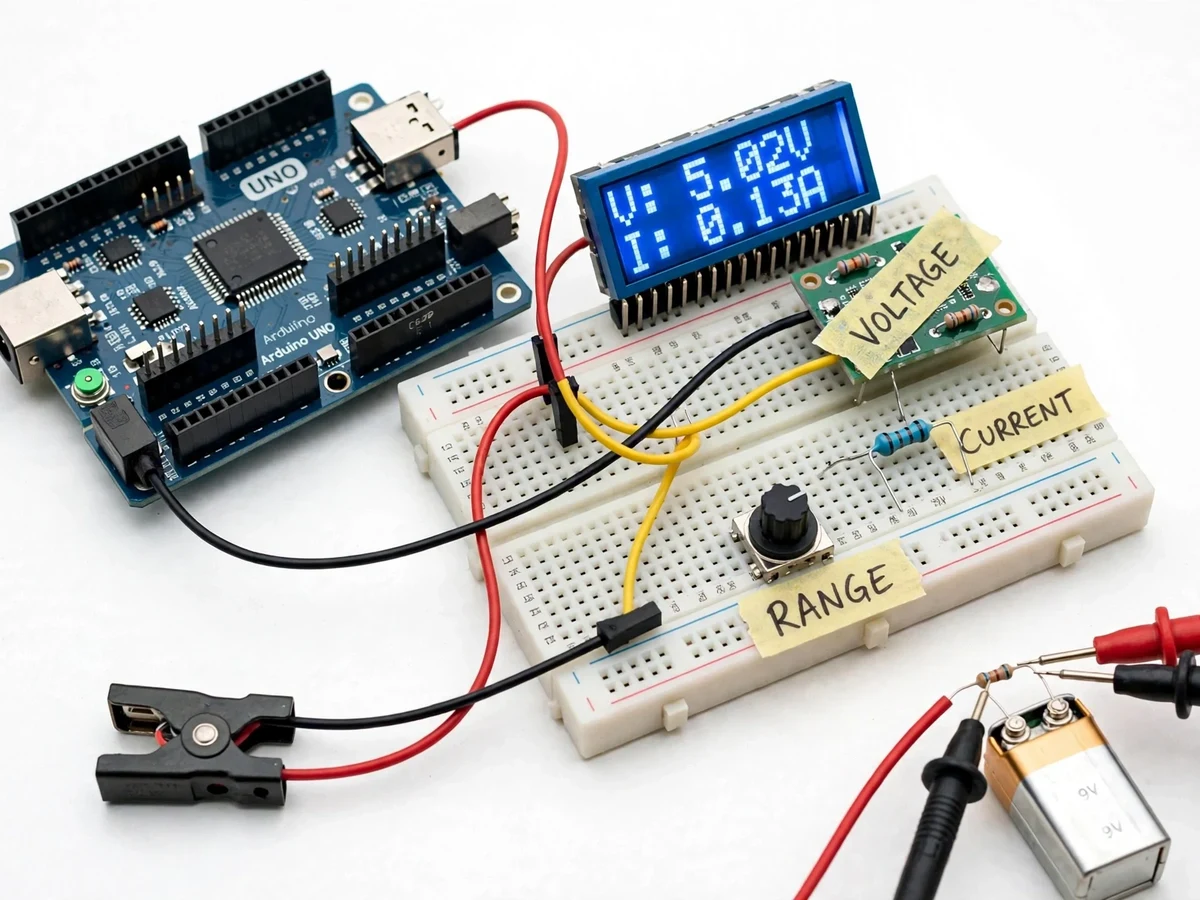
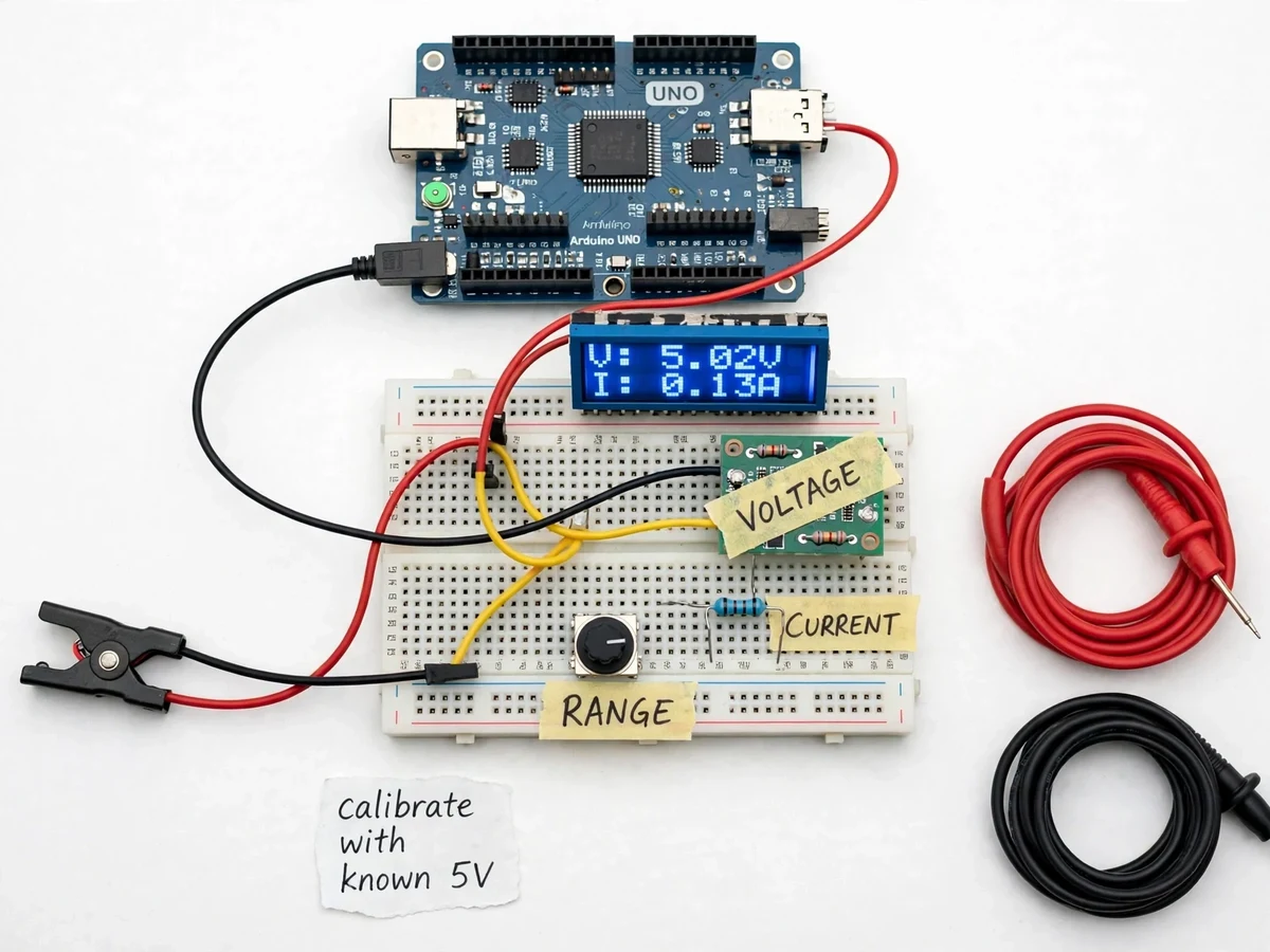
A DIY digital multimeter using Arduino is a working bench meter built around an Arduino Uno that measures DC voltage, DC current, resistance and continuity, and changes its own measurement range automatically. The Arduino Uno reads every quantity through its ATmega328P analogue-to-digital converter, after the input has been scaled down to the 0–5 V window the converter can accept. Students and hobbyists who repair circuits, test batteries or debug prototypes need a meter, yet a commercial handheld meter hides all of its measurement thinking inside a chip, so nothing about voltage dividers, shunt resistors or ranging is visible to learn from. Buying one also means accepting the manufacturer's ranges and accuracy. Building the meter instead turns the instrument itself into the lesson: every reading on the 16x2 LCD can be traced back to a resistor value, a divider ratio and a line of firmware, which is exactly the measurement electronics that electronics and electrical courses expect students to understand.
Red and black probes bring the unknown voltage, current or resistance to the input terminals.
Follow the working sequence
How it works
The DIY digital multimeter using Arduino turns an unknown electrical quantity into a number on a display in five stages. The test probes bring the unknown voltage, current or resistance to the input terminals, where a divider network or shunt resistor scales it into the 0–5 V window the Arduino can read. The ATmega328P's 10-bit ADC converts that scaled voltage into a count between 0 and 1023, with each step worth 4.88 mV at a 5 V reference. The firmware multiplies the count by the divider ratio or shunt value to recover the real-world quantity, checks whether the reading sits near the top or bottom of the current range, and switches a relay or MOSFET to a different divider tap when a better range exists. Finally the result, its unit and the active range are written to the 16x2 LCD, and a buzzer sounds in continuity mode when the measured resistance falls below the threshold.
- The red and black test probes connect to the circuit under test, and the rotary selector chooses voltage, current, resistance or continuity mode.
- For voltage, a switched divider network scales the input down to the 0–5 V window the Arduino ADC can accept; for current, the load flows through a low-value shunt resistor.
- The ATmega328P's 10-bit ADC samples the scaled voltage and returns a count between 0 and 1023, with each step worth 4.88 mV at a 5 V reference.
- The firmware averages several samples to suppress ADC noise, then multiplies the count by the divider ratio or divides the shunt drop by the shunt resistance to recover the real value.
- The firmware checks where the reading sits in the current range and switches a relay or MOSFET to a different divider tap when a higher or lower range fits better.
- The result, its unit and the active range are shown on the 16x2 LCD, and the buzzer sounds in continuity mode when the measured resistance falls below the threshold.
- Before first use, the meter is calibrated against a known 5 V source so the firmware's calibration factor corrects for the actual reference voltage and resistor tolerances.
Tech stack:
- Arduino Uno (ATmega328P)
- Arduino IDE · C/C++ firmware
- 16x2 LCD display
- Relay · MOSFET range switching
- Voltage divider networks
- Shunt resistor current sensing
- 5.1 V Zener input protection
- 9 V battery · 5 V USB power
| Parameter | Value |
|---|---|
| Controller | Arduino Uno (ATmega328P, 10-bit ADC, datasheet) |
| ADC resolution | 4.88 mV per step at 5 V reference, ±2 LSB absolute accuracy (datasheet) |
| DC voltage ranges | 0–5 V, 0–25 V and 0–50 V (design target, relay-switched) |
| DC current range | 0–2 A via shunt resistor (design target) |
| Resistance range | 0–100 kΩ via reference divider (design target) |
| Continuity threshold | Buzzer below approximately 50 Ω (design target) |
| Display | 16 × 2 character LCD (2 lines × 16 characters) |
| Input protection | 5.1 V Zener clamp with series resistor (datasheet practice) |
| Power supply | 9 V battery or 5 V USB, approximately 80 mA draw (expected) |
| Reading accuracy | Approximately ±2% after calibration (expected, not a measured claim) |
Project features
The DIY digital multimeter using Arduino measures four quantities from one set of test probes: DC voltage, DC current, resistance and continuity. Auto-ranging sits at the centre of the build: relay-switched divider taps let the firmware step between a sensitive low range and a wider high range without the user turning a dial, so a 1.5 V cell and a 24 V supply are both read on the most suitable scale. Current is read as the small voltage drop across a low-value shunt resistor and converted with Ohm's law, while resistance is measured against a known reference resistor in a divider. A continuity buzzer sounds when the probes meet a low-resistance path, and every result appears on a 16x2 LCD with its unit. Input protection clamps stray over-voltage before it reaches the Arduino, and the firmware averages several ADC samples so the last digit on the display stays steady instead of flickering.
- [Auto-ranging DC voltage] Relay-switched divider taps let the firmware pick the best range for the input, so small cell voltages and larger supply rails are both read without manual range selection.
- [DC current via shunt resistor] The load current flows through a low-value shunt resistor and the firmware converts the small voltage drop across it into amperes using Ohm's law.
- [Resistance measurement] An unknown resistor is measured against a known reference resistor in a divider, and the firmware calculates its value from the divider ratio.
- [Continuity buzzer] A buzzer sounds when the probes meet a low-resistance path, so broken wires and short circuits can be checked without watching the display.
- [16x2 LCD readout] Every reading is shown with its value, unit and active range on a two-line character LCD, readable from across a workbench.
- [Input protection] A series resistor and a 5.1 V Zener clamp keep accidental over-voltage away from the Arduino analogue pins.
- [Averaged and calibrated readings] The firmware averages several ADC samples per reading and applies a calibration factor set against a known 5 V reference, keeping the displayed digit steady.
What is included
- Working Arduino digital multimeter prototype with test probes
- Complete firmware source code with auto-ranging and calibration routines
- Circuit diagram and wiring documentation for the divider, shunt and protection stages
- Component list with resistor values and part numbers
- Calibration procedure using a known 5 V reference source
- Project abstract PDF (background, methodology, specifications, applications)
- Demonstration guidance for voltage, current, resistance and continuity tests
Limitations & prerequisites
- DC measurements only — AC voltage and AC current are not measured by this build.
- Reading accuracy is limited by the 10-bit ADC (±2 LSB, datasheet) and resistor tolerances; approximately ±2% after calibration is expected, not laboratory-grade accuracy.
- The DC current range is a 0–2 A design target and the shunt resistor warms up at sustained high current, so long high-current readings drift.
- The 5 V USB rail typically varies between about 4.7 V and 5.2 V, so readings drift unless the meter is calibrated against a known reference.
- This is an academic prototype, not a CAT-rated safety meter — never use it on mains supply or high-energy circuits.
- Resistance mode cannot measure a resistor reliably while it is still soldered into a circuit with other components in parallel.
Frequently Asked Questions
Which controller is used and why?
The Arduino Uno, built around the ATmega328P, is used because its 10-bit ADC converts a 0–5 V input into a count from 0 to 1023, which is exactly the measurement core a digital multimeter needs, and it has enough digital pins to drive the LCD, the range-switching relays and the buzzer from one board. Its large community and simple toolchain also make the firmware easy to explain and modify during a review.
How does auto-ranging actually work?
The firmware watches where each reading sits inside the active range and switches divider taps when a better range fits, so a reading crowding the top of the low range moves to a wider divider while a small reading drops back to the sensitive range. The active range is shown on the LCD next to the value, so the user always knows which scale produced the reading.
How accurate is it compared with a shop-bought multimeter?
It is accurate enough for lab and coursework measurements, with an expected accuracy of approximately ±2% after calibration, but it is not a replacement for a calibrated commercial meter, which uses a higher-resolution converter and factory calibration for serious test work. The 10-bit ADC alone contributes ±2 LSB of error (datasheet) and resistor tolerances add more, so this build is a learning instrument, not a test-lab instrument.
What power supply does it need?
The meter runs from a 9 V battery or from 5 V USB power, drawing approximately 80 mA, so it works on a bench or away from a wall socket, and battery power is the better choice because the 5 V USB rail typically varies between about 4.7 V and 5.2 V. That variation shifts the ADC reference, so the calibration step against a known 5 V source should be repeated whenever the supply changes.
Can it measure AC voltage or mains supply?
No, this build measures DC quantities only and must never be connected to mains supply, because AC measurement would need an additional rectifier and RMS conversion stage, and mains work needs CAT-rated insulation and fusing that a breadboard prototype does not have. The input protection only guards against modest over-voltage mistakes on low-voltage DC circuits.
Is this project suitable for a final-year project?
Yes, for Electronics & Telecommunication and Electrical Engineering programs, because it demonstrates analogue measurement, ADC interfacing, divider and shunt design, relay switching and calibration in one working instrument, and the report shows the divider calculations, ADC resolution maths and calibration procedure. That gives examiners concrete engineering to discuss, rather than a black-box meter.
Components & software requirements
- Arduino Uno (ATmega328P)
- Arduino IDE · C/C++ firmware
- 16x2 LCD display
- Relay · MOSFET range switching
- Voltage divider networks
- Shunt resistor current sensing
- 5.1 V Zener input protection
- 9 V battery · 5 V USB power
Delivery information
Built-to-order project. Delivery timeline is shared after order confirmation based on current queue.
Support terms
Complete documentation, setup guide, and viva preparation included. Support for setup and explanation provided.
Download free synopsis (PDF)
Enter your name and WhatsApp number — the synopsis PDF downloads immediately. We may send occasional project updates on WhatsApp; no spam.