
More project photos (2)
The problem
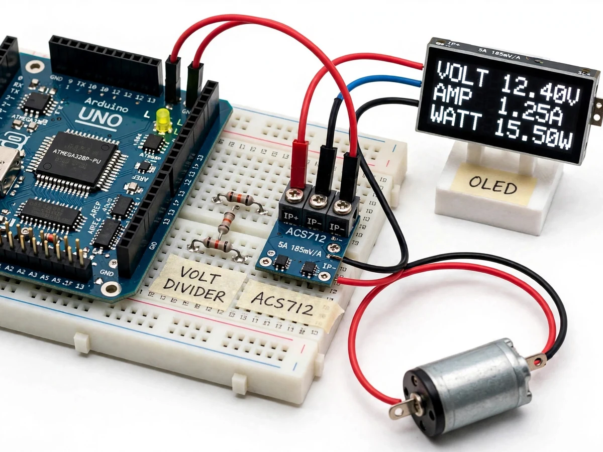
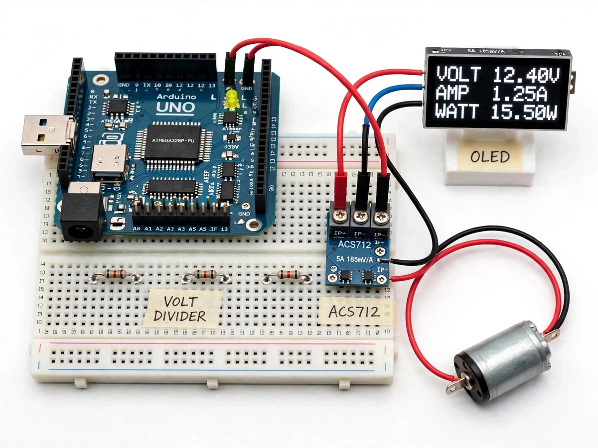
The Arduino Digital Voltmeter and Ammeter with OLED Display is a bench instrument that measures a DC circuit's voltage and current at the same time and shows both values, plus calculated power, on a small OLED screen. Students and hobbyists usually check voltage and current with a handheld multimeter, moving one set of probes between points and reading one quantity at a time, which makes it hard to watch how a load behaves while it runs. This project removes that juggling: a resistor divider scales the voltage down for the Arduino, a Hall-effect sensor reads the current without breaking the circuit's ground path, and the Arduino converts, averages and displays all three numbers continuously. The result is a working meter that can be left connected to a battery, charger or small motor while its behaviour is observed, explained and demonstrated.
Scales the circuit voltage down to the 0-5 V Arduino range.
Follow the working sequence
How it works
The Arduino Digital Voltmeter and Ammeter with OLED Display works by turning two physical quantities into numbers, then into text on a screen, in one continuous loop. Voltage reaches the Arduino through a resistor divider that scales the measured voltage down to the 0–5 V range the Arduino's analog input can accept, while current passes through an ACS712 Hall-effect sensor that produces a voltage proportional to the current flowing through it. The Arduino reads both voltages with its analog-to-digital converter, applies the divider ratio and the sensor sensitivity to recover real volts and amps, and averages several samples to calm noise. It then multiplies voltage by current to obtain power, checks both readings against the design range, and writes voltage, current and power to the OLED display over I2C, repeating the whole cycle about twice per second.
- The DC source and load are connected so that the voltage divider taps the voltage across the load, while the ACS712 sensor sits in series with the load so the full load current passes through it.
- Builder note: the divider uses a 30 kΩ resistor and a 7.5 kΩ resistor, giving a 5:1 ratio, so an input of 25 V appears as 5 V at the Arduino pin and the divider draws only about 0.67 mA at full input, limiting loading on the circuit under test.
- The Arduino samples the divider output and the ACS712 output on two analog inputs, averaging several samples on each channel to reduce noise before any conversion is applied.
- Voltage is recovered by multiplying the divider reading by the divider ratio, and current is recovered by subtracting the stored zero-current offset from the sensor reading and dividing by the sensor sensitivity.
- Power is calculated as voltage multiplied by current, and both readings are checked against the design range so an out-of-range input triggers the over-range warning.
- The three values are formatted with units and sent to the SSD1306 OLED display over I2C, refreshing about twice per second for a steady, readable screen.
- Pressing the freeze button holds the displayed values for noting down, and pressing it again resumes live updating without restarting the measurement loop.
Tech stack:
- Arduino Uno
- ACS712-05B Hall-effect current sensor
- Resistor-divider voltage sensing
- SSD1306 OLED display · I2C
- Arduino IDE
- Moving-average filtering in firmware
- Solderless breadboard prototype
- Jumper wiring · screw terminals
| Parameter | Value |
|---|---|
| Controller | Arduino Uno · ATmega328P microcontroller |
| Voltage measurement | Resistor divider · 0–25 V DC (design target · 5:1 ratio) |
| Divider resistors | 30 kΩ and 7.5 kΩ resistors (design choice) |
| Current measurement | ACS712-05B Hall-effect sensor · ±5 A DC (datasheet range) |
| Current sensitivity | 185 mV per A (datasheet value · 5 A variant) |
| Sensor zero-current output | 2.5 V at zero current (datasheet value · half of 5 V supply) |
| ADC resolution | 10-bit · 4.88 mV per step at 5 V reference (datasheet value) |
| Display | 0.96-inch SSD1306 OLED · 128 × 64 pixels · I2C interface |
| Power readout | Calculated as voltage × current · displayed in watts |
| Display refresh | Approximately 2 readings per second (design target) |
| Meter supply | 5 V USB or 7–12 V barrel-jack input (Arduino Uno input range) |
| Accuracy | Approximate · depends on resistor tolerance and calibration · no measured accuracy claimed |
Project features
The Arduino Digital Voltmeter and Ammeter with OLED Display is built around four headline capabilities that work together as one instrument. First, it shows voltage and current side by side on a single OLED screen, so a load's behaviour can be read at a glance without swapping probes or instruments. Second, it calculates and displays electrical power from those two readings, turning two separate measurements into one useful answer about what a circuit is actually consuming. Third, it steadies the display with averaging and a stored zero-current offset, so the last digit does not flicker uselessly on every refresh. Fourth, it warns clearly when an input goes beyond its design range instead of silently showing a clipped or misleading number. Around those four capabilities sit practical touches such as a freeze button for noting a reading and a compact breadboard layout that is easy to wire, test and explain.
- [Simultaneous voltage and current display — Implemented] Voltage and current appear together on the OLED screen, updated about twice per second, so a load's behaviour can be watched as it changes rather than measured one quantity at a time.
- [Calculated power readout — Implemented] Power in watts is computed in firmware as voltage multiplied by current and shown alongside both readings, giving one direct answer for what a battery, charger or motor circuit is consuming.
- [Averaged stable readings — Implemented] Several analog samples are averaged before display, so supply noise and small load fluctuations do not make the last digit jump on every refresh.
- [Zero-current offset calibration — Implemented] With no load connected, the firmware samples the ACS712 output and stores that value as the zero-current offset, then subtracts it from every later reading. Current is never measured directly: the sensor turns a magnetic field into a voltage, and the code turns that voltage back into current, so this calibration step is what makes the instrument trustworthy.
- [Clear OLED layout with units — Implemented] Each reading is labelled with its unit (V, A and W) in large, high-contrast text, so the screen can be read from a normal bench distance without guessing which number is which.
- [Over-range warning — Implemented] When an input exceeds the design range, the display shows an over-range warning instead of a clipped value, so an out-of-range measurement is never mistaken for a valid reading.
- [Freeze button — Implemented] A push button holds the current screen so a reading can be noted down, and a second press resumes live updating.
Optional customizations (not in the base build): AC measurement, data logging to a memory card, a larger display, relay-based over-current cut-off, and Bluetooth or Wi-Fi reporting. Future scope (not implemented): auto-ranging voltage input, a calibrated accuracy claim verified against a reference meter, and a mains-isolated measurement front end.
What is included
- Working Arduino voltmeter and ammeter prototype on breadboard
- Arduino firmware with averaging, offset calibration, power calculation and over-range warning
- Circuit diagram and wiring documentation
- Component list with divider resistor values and sensor variant
- Setup and calibration instructions, including the zero-current offset procedure
- Project report PDF (background, design, methodology, results discussion)
- PPT presentation for review
- Q&A preparation document covering ADC scaling, Hall-effect sensing and divider design
- Project abstract PDF
Limitations & prerequisites
- DC measurement only in the base build — AC voltage and AC current are not measured.
- Design voltage range is 0–25 V DC and design current range is ±5 A DC — inputs beyond these ranges trigger the over-range warning and must not be applied.
- Not a calibrated laboratory instrument and not certified for mains-voltage work — mains circuits must never be connected to this prototype.
- Readings depend on resistor tolerance, ACS712 offset drift and supply stability, so accuracy is approximate until calibrated against a known reference meter.
- Display refresh is approximately 2 readings per second (design target), so very fast load transients are not captured in detail.
- Breadboard prototype construction suits bench and demonstration use, not permanent or outdoor installation.
Frequently Asked Questions
Which controller is used and why?
The project uses an Arduino Uno, whose ATmega328P microcontroller provides the analog inputs, the 10-bit analog-to-digital conversion and the I2C interface that this meter needs, so no second controller or external converter is required, and the same board also drives the display and reads the freeze button for the base build. Its 5 V logic also matches the ACS712 sensor and the divider output directly, which keeps the wiring simple and the firmware easy to follow in a review.
How does it measure voltage and current?
Voltage is measured through a resistor divider that scales the circuit voltage down to the Arduino's 0–5 V analog input range, and current is measured by an ACS712 Hall-effect sensor placed in series with the load, which outputs a voltage proportional to the current flowing through it. The firmware then reverses both scalings: it multiplies the divider reading by the divider ratio to recover volts, and it subtracts the sensor's zero-current voltage and divides by its sensitivity to recover amps.
What does the OLED display show?
The OLED display shows voltage in volts, current in amps and calculated power in watts on one screen, updated about twice per second, so all three quantities for the same moment can be read together without switching modes, while the circuit under test keeps running. A freeze button holds the current screen so a reading can be noted down, and an over-range warning replaces the value when an input exceeds the design range.
Does it work without internet or a computer?
Yes, the meter works completely offline in normal everyday use once it is powered, because sensing, conversion, averaging and display all run on the Arduino itself with no cloud service, phone app, computer connection, network configuration, account or subscription involved at all. A computer is needed only during development, to upload the firmware through the Arduino IDE, and it is not needed for normal measurement afterwards.
What are the main limitations?
The base build measures DC only within its design range, it is not a calibrated laboratory instrument, and its readings depend on resistor tolerance, sensor offset and supply stability, so it must not be used where certified accuracy or mains-voltage safety is required. AC measurement, mains voltages and currents above the sensor range are out of scope, and accuracy improves only with careful offset calibration against a known reference meter.
Is this project suitable for a final-year project?
Yes, this project suits Electronics and Telecommunication students because it demonstrates analog sensing, resistor-divider design, Hall-effect current sensing, analog-to-digital conversion, averaging and filtering, I2C display interfacing and power calculation in one complete working instrument that can be demonstrated live during a review. It also gives a clear demonstration story: connect a battery or motor, watch voltage, current and power change together, and explain every conversion step from sensor voltage to displayed value.
Components & software requirements
- Arduino Uno
- ACS712-05B Hall-effect current sensor
- Resistor-divider voltage sensing
- SSD1306 OLED display · I2C
- Arduino IDE
- Moving-average filtering in firmware
- Solderless breadboard prototype
- Jumper wiring · screw terminals
Delivery information
Built-to-order project. Delivery timeline is shared after order confirmation based on current queue.
Support terms
Complete documentation, setup guide, and viva preparation included. Support for setup and explanation provided.
Download free synopsis (PDF)
Enter your name and WhatsApp number — the synopsis PDF downloads immediately. We may send occasional project updates on WhatsApp; no spam.