
More project photos (2)

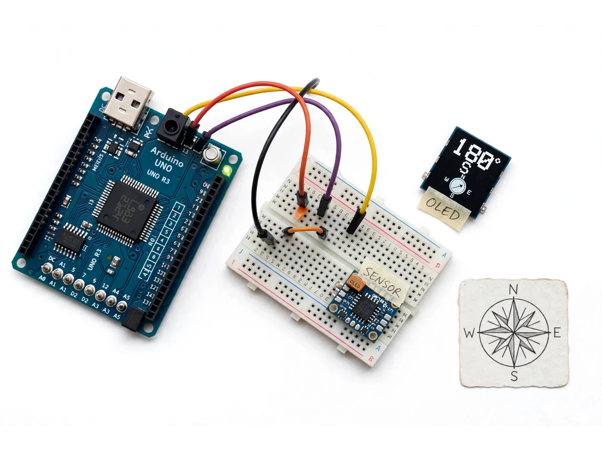
The problem
A digital compass is an instrument that finds direction by measuring Earth's magnetic field instead of using a magnetic needle. This project builds one with a QMC5883L magnetometer: an Arduino reads the sensor's X and Y field values, calculates heading with atan2, and shows degrees plus a compass point on an OLED display, after full-circle calibration removes magnetic offsets.
| Compass | How it finds direction | What it needs | Best for |
|---|---|---|---|
| QMC5883L digital compass | Measures X, Y and Z magnetic field components and computes heading | Arduino, sensor, OLED display and a power source | Learning magnetometers, calibration and embedded displays |
| Magnetic needle compass | A magnetised needle aligns with Earth's magnetic field | No power, but a level hand and a clear view of the needle | Simple navigation with no electronics |
| Phone compass app | Uses the phone's built-in magnetometer and software | A charged phone with a calibrated sensor | Everyday directions when a phone is at hand |
The digital compass project solves a practical learning problem: a needle compass shows direction but cannot feed a number into a circuit, a robot or a display, and a phone compass hides every step behind an app. Students who only use a phone never see how a magnetic field becomes a heading in degrees. This project makes that chain visible and testable: the QMC5883L senses the field on three axes, the Arduino turns the horizontal components into a 0° to 360° heading, and the OLED shows the result at once, so turning the unit through north, east, south and west can be checked against a printed compass rose. Calibration is part of the build, not an afterthought, because every nearby magnet, motor and metal frame shifts the raw reading. The finished unit is a compact bench and demonstration instrument for sensor interfacing, I2C communication and signal handling.
The magnetic field around the sensor.
Follow the working sequence
How it works
The digital compass project works as one short chain: the QMC5883L measures Earth's magnetic field on three axes, the Arduino corrects those readings with stored calibration offsets, converts the horizontal X and Y components into a heading with atan2, smooths the result, and draws degrees, compass point and a needle dial on the OLED. Calibration matters because the sensor also picks up fixed magnetic offsets from its own board and surroundings; rotating the unit through a full circle exposes the extremes of each axis, and the midpoint of each pair becomes the offset that is subtracted before the heading is computed. Keeping the sensor level matters too, since the calculation uses the horizontal plane. The same chain also explains the two things a reviewer will test first: turning the unit changes only the heading, and repeating the calibration after moving the unit restores a steady reading.
- The QMC5883L magnetometer measures the magnetic field on its X, Y and Z axes and sends the readings to the Arduino over I2C.
- The Arduino subtracts the stored calibration offsets from the X and Y readings to remove fixed magnetic bias from the board and surroundings.
- Heading is calculated from the corrected values with atan2(Y, X), converted from radians to degrees, and wrapped into the 0° to 360° range.
- A short average of recent samples steadies the heading so the display does not flicker when the unit is held still.
- The heading is mapped to the nearest of 8 compass points, and the OLED draws the degree value, the compass point and a small needle dial.
- In calibration mode, the user rotates the unit slowly through a full circle while the firmware records the minimum and maximum X and Y values and saves the new offsets.
- A declination offset, where set in the firmware, is added so the displayed heading can be read against true north instead of magnetic north.
Tech stack:
- Arduino Uno
- QMC5883L magnetometer · GY-271 module
- SSD1306 OLED display · I2C
- Arduino IDE · C++
- I2C communication
- Breadboard · jumper wiring
| Parameter | Value |
|---|---|
| Controller | Arduino Uno (ATmega328P board) |
| Sensor | QMC5883L 3-axis AMR magnetometer · 16-bit ADC (datasheet) |
| Magnetic field range | ±2 to ±20 gauss, selectable by gain setting (datasheet) |
| Field resolution | 2 milli-gauss (datasheet) |
| Interface | I2C, standard and fast modes (datasheet) |
| Display | SSD1306 OLED display · 128 × 64 pixels |
| Heading output | 0° to 360° with 8 compass points |
| Data output rate | Up to 200 Hz maximum (datasheet) |
| Supply voltage | 3.3 V to 5 V at the GY-271 module |
| Heading accuracy | ±3° (design target, not a measured claim) |
Project features
The digital compass project centres on four capabilities: a live heading readout in degrees with its compass point, a guided full-circle calibration routine, a raw magnetic-field readout for checking the sensor, and a steadied display reading that averages noisy samples. Together they let a student demonstrate the sensor, prove the calibration and explain each number on screen, rather than only showing a dial that moves. The live readout answers the first question any visitor asks — which way is this pointing — in degrees and in plain compass language at the same time. The calibration routine answers the second — can the reading be trusted near a real board — by measuring the sensor's own offsets instead of assuming a perfect sensor. The raw-field screen and the averaged output complete the story for a reviewer: one shows the unprocessed evidence, the other shows why the displayed number does not jump with every small sample.
- [Live heading display — Implemented] The OLED shows heading from 0° to 360°, the nearest of 8 compass points (N, NE, E, SE, S, SW, W, NW) and a small rotating needle dial, updated continuously as the unit turns.
- [Guided calibration routine — Implemented] On demand, the firmware prompts the user to rotate the unit slowly through a full circle, records the minimum and maximum X and Y readings, and stores the resulting offsets for later use.
- [Raw field readout mode — Implemented] A second display screen shows the calibrated X, Y and Z magnetic field values in milli-gauss, so the sensor behaviour behind the heading can be inspected and discussed.
- [Steadied heading output — Implemented] Successive samples are averaged before the heading is calculated, which smooths small jitter while the unit is held still, without hiding genuine turns.
- [Magnetic declination setting — Configurable] A declination offset in degrees can be set in the firmware, so the display can be adjusted from magnetic north toward true north for the place of use.
- [Heading-alert buzzer — Optional customization] A buzzer that sounds when the heading enters a chosen sector can be added on request; it is not part of the base build.
- [Tilt-compensated heading — Future scope] Adding an accelerometer and tilt compensation so heading stays correct when the unit is tilted is a possible extension, and it is not included in the base build.
What is included
- Assembled digital compass prototype (Arduino, QMC5883L module, OLED display, breadboard wiring)
- Arduino firmware source code with calibration routine and declination setting
- Wiring diagram and component list
- Step-by-step calibration and demonstration procedure
- Project report PDF (background, magnetometer theory, methodology, results format)
- PPT presentation for review
- Viva Q&A preparation document (magnetometers, I2C, atan2 heading, calibration, interference)
Limitations & prerequisites
- Heading accuracy of ±3° is a design target, not a measured result; the built unit must be checked against a known reference direction after calibration.
- Nearby motors, magnets, phones, laptops and steel furniture distort the field and shift the heading; readings must be taken away from such sources.
- The sensor must stay level during use: tilting the unit changes the X and Y projection, and tilt compensation is not included in the base build.
- The display shows magnetic north by default; true north needs the declination offset set for the place of use.
- Indoor steel structures can bend the local field, so the same heading may read differently in different rooms.
- The unit gives direction only: it has no GPS, no position tracking and no navigation routing.
- This is an academic prototype, not a certified navigation instrument, and it must not be used for safety-critical navigation.
Frequently Asked Questions
How does this compass calculate heading?
It calculates heading from the horizontal magnetic field using atan2 of the corrected Y and X components, then converts the result to degrees from 0° to 360°. The Arduino first subtracts calibration offsets from both axes, so fixed magnetic bias does not skew the angle, and the OLED then shows the degree value with its compass point.
Why must the sensor be rotated through a full circle for calibration?
A full-circle rotation is needed because fixed magnetic offsets shift the whole reading circle away from zero on each axis. Turning the sensor through 360° exposes the minimum and maximum value on X and on Y, and the midpoint of each pair is the offset to subtract. Without this step, the heading carries a constant error that changes with direction.
What can disturb the reading?
Motors, magnets, phones, laptops, steel furniture and reinforced walls can all distort the local magnetic field and shift the heading. The unit should be used away from such sources, and recalibrated after it is remounted or moved near new metal. This sensitivity is a property of magnetic sensing itself, not a fault in one unit.
Does this project need internet or GPS?
No, it needs neither internet nor GPS, because heading comes purely from Earth's magnetic field measured by the QMC5883L. Power from USB or a battery is enough, and the OLED shows the heading on the unit itself. GPS would add position, which is a different function and is not part of this build.
Is this project suitable for a final-year project?
Yes, it fits Electronics, E&TC and Electrical programmes, and it demonstrates magnetometer interfacing, I2C communication, calibration mathematics and embedded display design. The calibration routine and the atan2 heading calculation give clear technical material to present and to defend in a review.
Components & software requirements
- Arduino Uno
- QMC5883L magnetometer · GY-271 module
- SSD1306 OLED display · I2C
- Arduino IDE · C++
- I2C communication
- Breadboard · jumper wiring
Delivery information
Built-to-order project. Delivery timeline is shared after order confirmation based on current queue.
Support terms
Complete documentation, setup guide, and viva preparation included. Support for setup and explanation provided.
Download free synopsis (PDF)
Enter your name and WhatsApp number — the synopsis PDF downloads immediately. We may send occasional project updates on WhatsApp; no spam.