
More project photos (2)
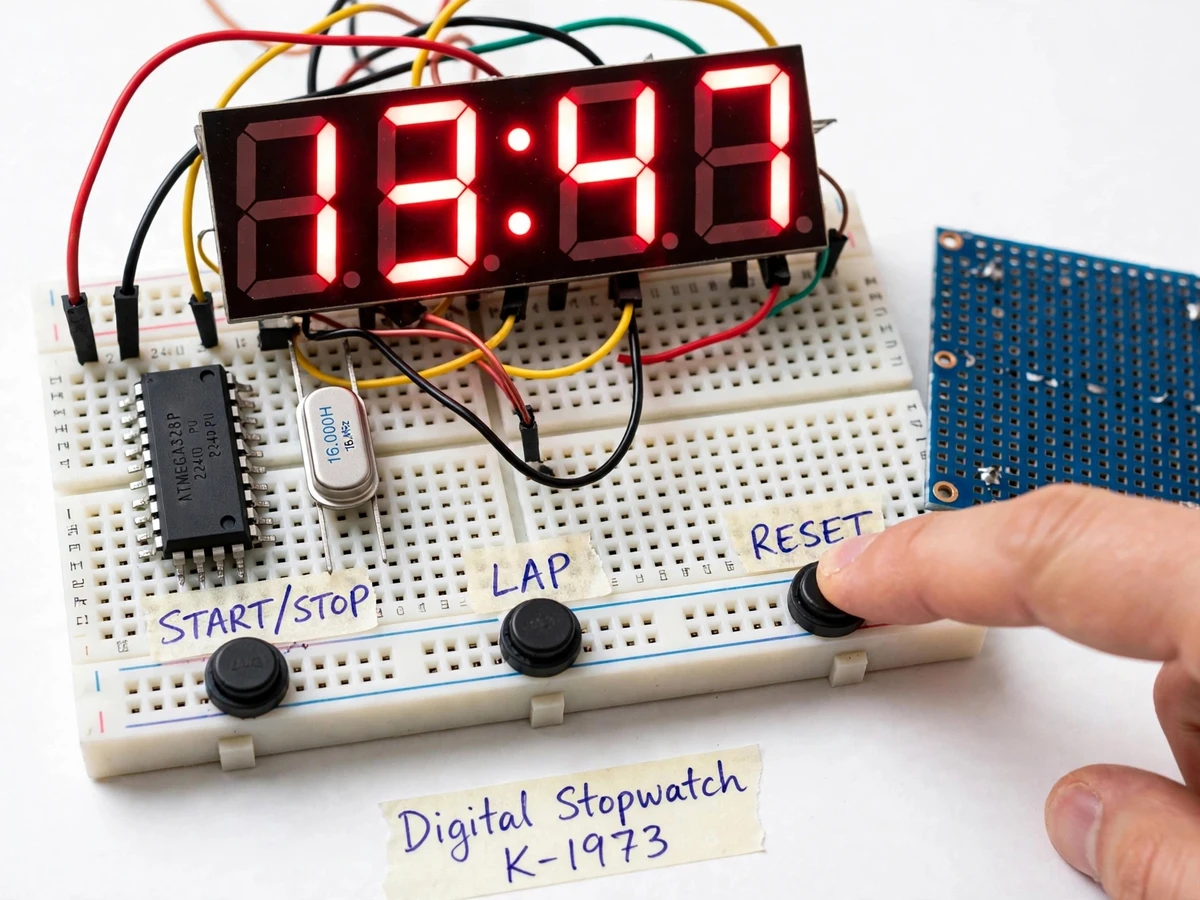
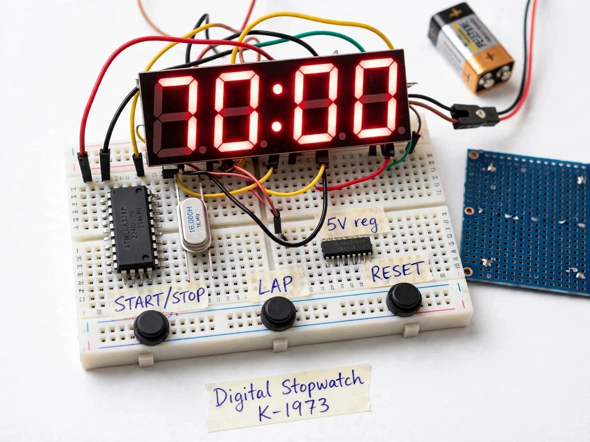
The problem
Timing is one of the most common measurements in engineering labs, yet the stopwatches students reach for are usually phone apps — their timing resolution is hidden behind the OS, their lap lists live behind a touchscreen, and they teach nothing about how time is actually counted in hardware. A student who wants to understand embedded timing has to learn the pieces a phone hides: how a hardware timer ticks independently of the CPU, how a microcontroller drives more display digits than it has pins, and how a button press becomes a stored timestamp. This project makes all three visible in one build. An ATmega328P counts time with its 16-bit Timer1 in interrupt mode, a 4-digit 7-segment display is multiplexed fast enough to look steady, and a LAP button writes each split time into the chip's internal EEPROM. The result is a real bench instrument for timing experiments, sports drills or lab measurements — and every subsystem maps directly to a viva question on timers, interrupts, multiplexing or memory.
16 MHz MCU; the Timer1 interrupt counts milliseconds while the main loop converts ticks to time and drives the display.
Follow the working sequence
How it works
- A 16 MHz crystal clocks the ATmega328P (datasheet); Timer1 is configured in CTC mode with a prescaler and compare value chosen to fire an interrupt every 1 ms (design value).
- The Timer1 interrupt service routine increments a 32-bit tick counter and nothing else, so timekeeping stays exact regardless of what the main loop is doing.
- The main loop converts the tick count into minutes, seconds and centiseconds, and drives the 4-digit display one digit at a time at roughly 160 Hz (design target) — fast enough that the eye sees all digits lit.
- Pressing START/STOP toggles a running flag (debounced over ~20 ms, design value); RESET clears the counter and the lap index.
- Pressing LAP while running freezes the displayed time and writes the 4-byte timestamp into EEPROM; the 32nd lap (design value) wraps the buffer and the oldest lap is overwritten.
- Pressing LAP while stopped enters recall mode, and each further press steps the display through the stored laps in order.
- A MODE press switches the display between MM:SS and SS.CC views so short intervals can be read to 10 ms resolution (design value).
Tech stack:
- ATmega328P (28-pin DIP) with 16 MHz crystal
- Embedded C compiled with avr-gcc
- 4-digit common-cathode 7-segment LED display, multiplexed
- Timer1 CTC compare-match interrupt (1 ms tick)
- On-chip 1 KB EEPROM for lap storage
- Tactile push buttons with software debounce
- 7805 regulator for 9 V battery operation
- Solderless breadboard / perfboard assembly
| Parameter | Value |
|---|---|
| Controller | ATmega328P, 28-pin DIP (datasheet: 32 KB flash, 2 KB SRAM, 1 KB EEPROM) |
| Clock source | 16 MHz crystal oscillator (datasheet-rated) |
| Timebase | Timer1 16-bit, CTC mode, 1 ms compare-match interrupt (design value) |
| Display | 4-digit 0.56-inch common-cathode 7-segment LED, multiplexed at ~160 Hz (design target) |
| Timing resolution | 10 ms in SS.CC mode, 1 s in MM:SS mode (design value) |
| Maximum count | 99 min 59 s, then rolls over (design value) |
| Lap memory | 32 laps in on-chip EEPROM, retained without power (design value; capacity per datasheet) |
| Buttons | 3 tactile 6 × 6 mm push buttons, ~20 ms software debounce (design value) |
| Time accuracy | Expected drift ±4 s/day from ±50 ppm crystal tolerance (expected, component-dependent) |
| Power | 5 V USB or 9 V battery via 7805; draw ~70 mA all segments lit (expected) |
Project features
- [Timer1 interrupt timebase] The 16-bit Timer1 peripheral runs in CTC mode off the 16 MHz crystal and fires a compare-match interrupt every 1 ms (design value), so the stopwatch counts in hardware and keeps time even while the main loop is busy refreshing the display.
- [Multiplexed 4-digit 7-segment display] The display shows MM:SS in run mode and SS.CC (centiseconds) in detail mode, refreshed at approximately 160 Hz (design target) with 220 Ω segment resistors (design value) so all four digits look steadily lit from only 12 microcontroller pins.
- [Start, stop and reset controls] Three debounced tactile buttons run the whole instrument: START/STOP toggles counting, RESET zeroes the counter, and every press is filtered by a ~20 ms software debounce (design value) to kill contact bounce.
- [Lap memory with EEPROM recall] Pressing LAP freezes the display and stores the timestamp in the ATmega328P's on-chip 1 KB EEPROM (datasheet) — up to 32 laps (design value) that survive power-off; while stopped, repeated LAP presses scroll through the stored laps on the display.
- [Crystal-accurate counting] The 16 MHz crystal oscillator (datasheet-rated) gives the timebase an expected drift of about ±4 s/day from ±50 ppm crystal tolerance (expected, component-dependent) — orders of magnitude steadier than the chip's internal RC oscillator.
- [Power-up lap recovery] On every boot the firmware reads the stored lap count from EEPROM, so a session's laps are still there after a battery change or accidental unplug.
- [Portable battery power] A 9 V battery through a 7805 regulator (or 5 V USB) runs the whole unit; expected draw is about 70 mA with all segments lit (expected), making it usable on a bench or a sports field.
What is included
- Assembled and tested stopwatch prototype (breadboard/perfboard build)
- Complete firmware source in Embedded C (avr-gcc) with comments
- Circuit and wiring diagram with pin mapping
- Component list with values and ratings
- Project report PDF (background, design, timer theory, methodology, testing)
- PPT presentation for the final review
- Viva Q&A document (timers, interrupts, multiplexing, EEPROM, debouncing)
- Lap test procedure: calibrate against a reference stopwatch over 10 minutes and record the deviation
- Demonstration and setup guidance
Limitations & prerequisites
- Timing accuracy is bounded by crystal tolerance: expected drift is about ±4 s/day (expected, component-dependent) — it is a student instrument, not a certified chronometer.
- The 4-digit display is readable indoors and at typical bench distances; it is not sunlight-readable.
- Button response includes ~20 ms of debounce (design value), so intervals below ~50 ms cannot be resolved by hand pressing anyway.
- Lap memory holds 32 laps (design value); the 33rd lap overwrites the oldest — there is no SD card or PC logging in the base build.
- A 9 V alkaline cell lasts approximately 5–8 hours of continuous display-on use (expected, usage-dependent).
- This is a bench prototype on breadboard/perfboard, not a sealed or weatherproof product.
- Display brightness and refresh rate are fixed in firmware; dimming is an optional customization.
Frequently Asked Questions
Which controller is used and why?
The ATmega328P in a 28-pin DIP package. It has a true 16-bit hardware timer (Timer1) for the 1 ms timebase, 1 KB of on-chip EEPROM for the lap memory, and enough GPIO to multiplex a 4-digit display — all breadboard-friendly and ideal for an embedded-timing viva.
How accurate is the stopwatch?
Timing comes from a 16 MHz crystal with an expected drift of about ±4 s/day (expected, component-dependent) — far steadier than the chip's internal RC oscillator. The report includes a calibration procedure: run it against a reference stopwatch for 10 minutes and note the deviation, which makes a solid testing section.
How many laps can it store, and do they survive power-off?
Up to 32 laps (design value), each timestamp written to the ATmega328P's internal 1 KB EEPROM (datasheet) the moment you press LAP. EEPROM is non-volatile, so laps survive battery changes, unplugging and accidental resets. While the stopwatch is stopped, pressing LAP repeatedly steps the display through the stored laps in the order they were recorded.
What power supply does it need?
The prototype runs on 5 V over USB or a 9 V battery through the on-board 7805 regulator. Expected current draw is about 70 mA with all display segments lit (expected), which gives roughly 5–8 hours of continuous use on a fresh 9 V alkaline cell (expected, usage-dependent). A bench USB supply works fine for lab demos.
Can a buzzer or a bigger display be added?
Yes. Realistic customizations include a lap-confirmation buzzer, a 6-digit display to show hours, or serial logging that streams lap times to a PC terminal. These are developed on request as optional additions; the base project ships with the 4-digit multiplexed display and silent push-button operation.
Is this project suitable for a final-year project?
Yes — for Electronics, E&TC and Instrumentation programs. It demonstrates hardware timers, compare-match interrupts, display multiplexing, EEPROM storage and button debouncing in one working instrument, and each subsystem maps cleanly to viva questions the student can answer from their own build. Suitable for B.E./B.Tech final-year projects in Electronics, E&TC and Instrumentation.
Components & software requirements
- ATmega328P (28-pin DIP) with 16 MHz crystal
- Embedded C compiled with avr-gcc
- 4-digit common-cathode 7-segment LED display, multiplexed
- Timer1 CTC compare-match interrupt (1 ms tick)
- On-chip 1 KB EEPROM for lap storage
- Tactile push buttons with software debounce
- 7805 regulator for 9 V battery operation
- Solderless breadboard / perfboard assembly
Delivery information
Built-to-order project. Delivery timeline is shared after order confirmation based on current queue.
Support terms
Complete documentation, setup guide, and viva preparation included. Support for setup and explanation provided.
Download free synopsis (PDF)
Enter your name and email — the synopsis PDF downloads immediately. We may send occasional project updates; no spam, unsubscribe anytime.