
More project photos (2)
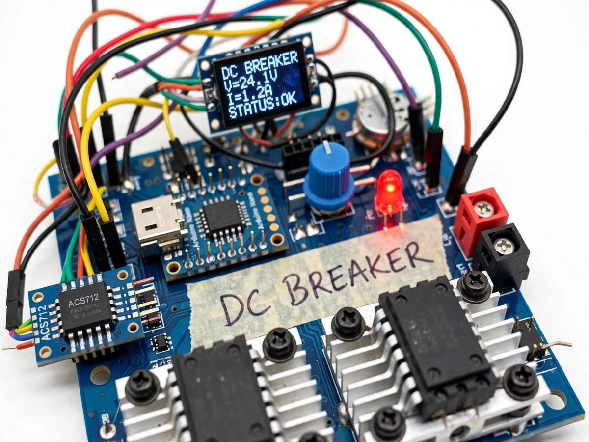
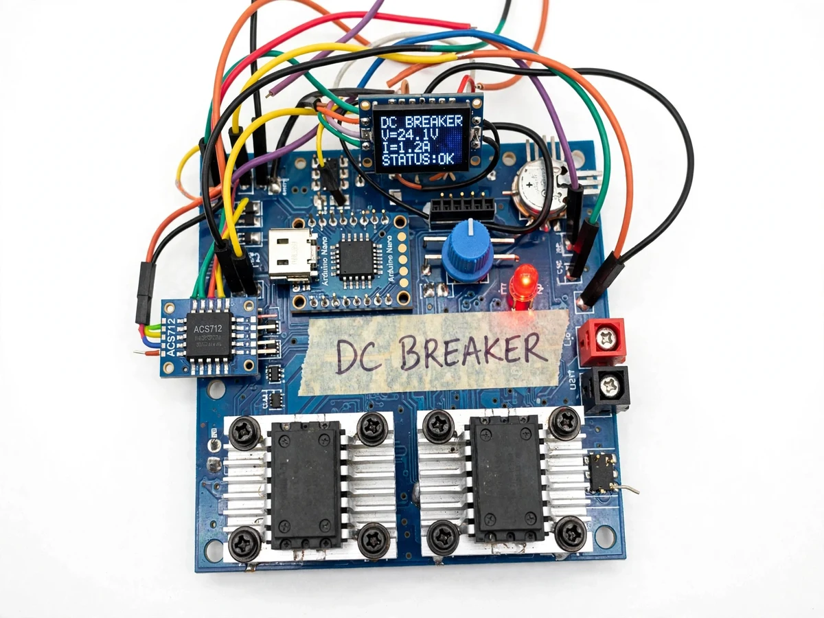
The problem
DC distribution is everywhere in student and prototype work — solar installations, battery banks, telecom supplies, EV auxiliary circuits — yet the protection most benches reach for is still the thermal-magnetic MCB, a device designed around AC mains behavior. In a DC circuit there is no natural current zero to quench an arc, and a thermal trip that takes seconds to react can let a shorted converter or a stalled motor destroy itself long before the contacts open. Fuses are faster but single-use and imprecise. An electronic DC breaker answers this with fully solid-state switching: power MOSFETs in the current path, a Hall-effect sensor watching current continuously, and a comparator stage that drops the gate drive the instant current exceeds a set threshold. The result is a resettable, adjustable protector that demonstrates genuine power-electronics concepts — gate driving, isolated current sensing, fault latching — in a compact 12–24 V prototype.
How it works
- The DC source (12–24 V battery or bench supply) feeds the load through the MOSFET pass element, with the ACS712 sensor in series producing a voltage proportional to load current.
- The sensor signal is filtered and fed to one input of the LM393 comparator; the other input carries the threshold reference set by the front-panel potentiometer.
- Under normal load the sensor voltage stays below the reference, the comparator output keeps the TC4420 gate driver enabled, and the MOSFETs stay fully on with milliohm-level on-resistance.
- When an overload or short drives current past the set threshold, the comparator flips and the gate driver pulls the MOSFET gates to ground — the pass element turns off and the load is isolated from the source.
- The controller latches the trip state, lights the red fault LED and freezes the peak current reading on the OLED for the fault analysis in the report.
- The output remains off until the user presses the front-panel reset button (or the configured auto-retry interval elapses), preventing repeated re-energization of a persistent fault.
- During normal operation the controller continuously samples the sensor and updates the OLED with live current, threshold and status.
Tech stack:
- Arduino Nano (ATmega328P) for monitoring, display and reset logic
- IRF3205-class N-channel power MOSFETs as the series switching element
- ACS712-20A Hall-effect current sensor (isolated measurement)
- LM393 comparator for the fast hardware trip path
- TC4420 MOSFET gate driver
- 0.96-inch I2C OLED display for current and status readout
- KiCad for schematic and PCB layout; Arduino IDE for firmware
- 12–24 V DC source and test load (bench supply / battery, user side)
| Parameter | Value |
|---|---|
| Input voltage | 12–24 V DC (design range) |
| Continuous current | Up to 10 A with specified heatsink (design target; heatsink- and ambient-dependent) |
| Trip threshold | Adjustable, approximately 2–10 A via front-panel potentiometer |
| Trip response | Design target under 100 µs from overcurrent to MOSFET turn-off (derived from component delays; buyer verifies with oscilloscope per included procedure) |
| Switching element | N-channel power MOSFETs (IRF3205 class), low-side solid-state switch |
| Current sensing | ACS712-20A Hall-effect, ±1.5% typical accuracy at 25 °C per datasheet |
| Trip behavior | Latch-off with manual reset; auto-retry available as configurable option |
| Display | 0.96-inch OLED: live current, set threshold, trip/fault status |
| Protection scope | Overcurrent and short-circuit on the DC load side only |
Project features
- [Solid-state MOSFET switching] N-channel power MOSFETs (IRF3205 class) form the series pass element. There are no moving contacts, no arcing and no contact wear, so the breaker can trip thousands of times where a relay-based cutoff would degrade.
- [Hall-effect current sensing] An ACS712-20A isolated sensor measures load current continuously without inserting a high-side shunt into the power path or disturbing the load ground. The controller sees true load current, including startup inrush.
- [Fast electronic trip] An LM393 comparator watches the sensor output against the threshold reference and pulls the MOSFET gate drive low on overcurrent. The design target is under 100 microseconds from fault to switch-off, derived from comparator and gate-driver propagation delays.
- [Adjustable trip threshold] The current limit is set with a front-panel potentiometer and read back on the display, so the same module demonstrates protection at 2 A for a small DC motor and 10 A for a battery bank.
- [Latch-off with manual reset] After a trip the output stays off until the reset button is pressed, so an intermittent short cannot repeatedly re-energize the load. An auto-retry mode is available as a configurable option.
- [Live current and status display] A 0.96-inch OLED shows measured current, the set threshold and trip/fault status, giving the examiner a visible, verifiable readout during the demonstration.
- [Inrush blanking for motor loads] A short configurable blanking window after switch-on ignores the normal startup surge of DC motors and capacitive loads, so the breaker trips on genuine faults rather than on turn-on transients.
What is included
- Assembled and wired DC electronic breaker prototype module
- Controller firmware (Arduino sketch) with threshold, inrush-blanking and reset logic
- Circuit schematic and wiring diagram (KiCad sources plus PDF)
- Bill of materials with part numbers and sourcing notes
- Project report PDF (background, design calculations, gate-drive and sensing design, buyer-run test procedure)
- PPT presentation for final review
- Viva Q&A preparation document (MOSFET switching, comparators, Hall-effect sensing, DC fault behavior)
- Setup and demo guide (wiring source and load, setting the threshold, demonstrating a trip safely)
Limitations & prerequisites
- This is an academic prototype, not a certified protection device: it must not be used as the sole protection on mains-connected, high-energy or safety-critical installations.
- The sub-100 µs trip figure is a design target derived from comparator and gate-driver propagation delays, not a value measured on a calibrated high-speed rig; the report includes a buyer-run oscilloscope procedure to verify it.
- The continuous current rating depends on MOSFET heatsinking and ambient temperature; sustained operation near 10 A needs the specified heatsink and airflow, confirmed by the buyer's thermal check.
- The prototype covers low-voltage DC (12–24 V) only; it provides no AC mains protection and no galvanic isolation between source and load beyond the MOSFET off-state.
- Prototype wiring inductance and layout affect real switching behavior; the supplied PCB layout keeps the power loop tight, but a hand-wired build will trip slower than the design target.
- Single-pole low-side switching only: the load's positive rail stays connected to the source when tripped, which the report explains and the demo wiring accounts for.
Frequently Asked Questions
Is this project suitable for a final-year project?
Yes — it fits Electrical and Electronics (and E&TC) programs and demonstrates power-electronics fundamentals examiners value: MOSFET switching, gate driving, isolated current sensing, comparator-based protection and DC fault behavior, all verifiable live on the bench.
Which controller and switching devices are used?
An Arduino Nano handles monitoring, the OLED readout and reset logic; the power path uses IRF3205-class N-channel MOSFETs driven by a TC4420 gate driver, with an ACS712-20A Hall sensor for current measurement and an LM393 comparator for the fast trip path.
Can it protect AC mains or high-voltage DC?
No. The design is strictly for low-voltage DC (12–24 V). AC protection needs zero-crossing and arc-management behavior this circuit does not implement, and high-voltage DC needs different clearances and devices.
How fast does it actually trip?
The design target is under 100 µs from overcurrent to MOSFET turn-off, derived from the comparator and gate-driver propagation delays. The report includes a buyer-run oscilloscope procedure so you can verify the actual trip time on your own build rather than taking a number on faith.
Can the trip current be changed?
Yes — a front-panel potentiometer sets the threshold (approximately 2–10 A) and the OLED shows the set value live, so you can demonstrate different protection levels on different loads.
What will I receive with the project?
The assembled breaker module, controller firmware, schematic and wiring diagrams, bill of materials, project report PDF, PPT, viva Q&A document and a setup/demo guide. Suitable for B.E./B.Tech final-year projects in Electrical and Electronics Engineering.
Components & software requirements
- Arduino Nano (ATmega328P) for monitoring, display and reset logic
- IRF3205-class N-channel power MOSFETs as the series switching element
- ACS712-20A Hall-effect current sensor (isolated measurement)
- LM393 comparator for the fast hardware trip path
- TC4420 MOSFET gate driver
- 0.96-inch I2C OLED display for current and status readout
- KiCad for schematic and PCB layout; Arduino IDE for firmware
- 12–24 V DC source and test load (bench supply / battery, user side)
Delivery information
Built-to-order project. Delivery timeline is shared after order confirmation based on current queue.
Support terms
Complete documentation, setup guide, and viva preparation included. Support for setup and explanation provided.