
More project photos (2)
The problem
The IoT Smart Circuit Breaker with Remote Trip and Energy Monitoring is a protection-first electrical panel build: an ESP32 controller watches the current through a branch circuit, and when that current crosses a threshold or a remote trip command arrives, it drives a contactor open and cuts power to that circuit. This matters because a conventional miniature circuit breaker protects a circuit but tells the user nothing — nobody knows which circuit tripped, why it tripped, or how much energy it was carrying before the fault. A home, laboratory or hostel floor with several branch circuits stays dark longer than it needs to, and repeated unexplained trips never get diagnosed. This project closes that gap without pretending to be a certified protection device: it adds remote trip, trip-cause logging and energy visibility on top of a contactor trip element, so a fault is recorded, explained and cleared deliberately. It is a breaker that reports, not a meter that watches.
Builder note from the demo build: the trip latch was deliberately kept separate from the Wi-Fi reconnect logic, so a dropped connection can never re-close a tripped circuit — a trip stays a trip until a person resets it.
Measures voltage and current on the panel supply and reports them over a serial link.
Follow the working sequence
How it works
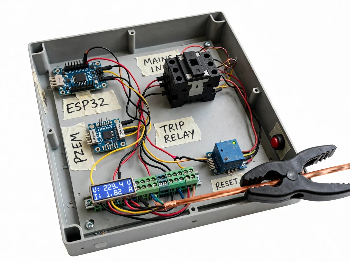
The IoT Smart Circuit Breaker with Remote Trip and Energy Monitoring works as a closed protection loop that starts with measurement and ends with a deliberate reset. The PZEM-004T module measures the voltage and current of each branch circuit and reports them to the ESP32 over a serial link, with sensing isolated from the mains conductor. The ESP32 compares the measured current against the configured threshold for that circuit, and it also listens for trip commands arriving from the dashboard over Wi-Fi; whichever comes first — a threshold crossing or a remote command — drives the trip relay, which drops the contactor coil and physically opens the circuit. On a trip, the controller records the event with its cause and timestamp, updates the dashboard, and latches the circuit open. Nothing re-closes it automatically: the user inspects the fault, then presses reset on the dashboard or the panel button, and only then does the contactor close again.
- The PZEM-004T module measures voltage and current on each branch circuit and sends the readings to the ESP32 over a serial link.
- The ESP32 compares each circuit's current against its configured threshold (adjustable from 10 A to 32 A) and checks for incoming trip commands from the dashboard.
- On a threshold crossing or a remote trip command, the ESP32 drives the trip relay, which drops the contactor coil and physically opens that circuit.
- The controller records the trip with a timestamp and its cause (remote command, overcurrent, or simulated fault) and updates the dashboard state to tripped.
- The trip latch holds the contactor open: no automatic re-close happens on Wi-Fi reconnect or power restore.
- The dashboard keeps showing live readings for the healthy circuits and the energy chart continues from the logged data.
- After the fault is inspected, the user presses reset on the dashboard or the panel button; only then does the contactor close and the circuit re-energise.
Tech stack:
- ESP32 microcontroller
- PZEM-004T energy meter module
- 40 A 2-pole contactor · trip relay
- Arduino IDE · ESP32 firmware
- HTML · CSS · JavaScript dashboard
- Wi-Fi · MQTT or HTTP telemetry
- 16x2 LCD local display
Hardware requirements
- ESP32 development board (dual-core, 240 MHz, datasheet value)
- PZEM-004T energy meter module with current transformer (80–260 V AC, 0–100 A, datasheet values)
- 40 A 2-pole contactor with 230 V AC coil (component rating)
- Relay module for the trip circuit
- 16x2 LCD display and panel reset push-button
- Enclosure, terminal blocks, DIN rail and mains-rated wiring
- 5 V DC supply for the controller and low-voltage electronics
Software requirements
- Arduino IDE with ESP32 board support (current stable release, design target)
- Single-file HTML/CSS/JavaScript dashboard (reference demo build included)
- Wi-Fi network for remote trip and dashboard access; local LCD works without Wi-Fi
| Parameter | Value |
|---|---|
| Controller | ESP32, dual-core 240 MHz (datasheet value) |
| Energy meter | PZEM-004T, 80–260 V AC, 0–100 A (datasheet values) |
| Trip element | 40 A 2-pole contactor, 230 V AC coil (component rating) |
| Branch circuits | 4 circuits in the reference build |
| Overcurrent threshold | 10–32 A (configurable) |
| Trip response | Under 0.5 seconds from threshold crossing to contactor open (design target) |
| Connectivity | Wi-Fi 2.4 GHz (ESP32 radio) |
| Local display | 16x2 LCD showing live voltage and current |
| Trip log | Timestamp plus cause for every trip event (stored on the controller) |
| Energy reporting | Voltage, current, active power and daily energy in kilowatt-hours |
| Supply | 230 V AC single-phase, 50 Hz nominal (Indian mains) |
| Prototype class | Academic prototype, not a certified MCB or RCCB replacement |
Project features
The IoT Smart Circuit Breaker with Remote Trip and Energy Monitoring stands on four capabilities as one protection loop: remote trip from the dashboard that opens a circuit on command, automatic overcurrent tripping that opens the contactor when current crosses the configured threshold, a latching trip state that holds the circuit open until a deliberate reset, and a trip log that records every event with its cause and timestamp. Around that loop sit the supporting pieces: live energy monitoring showing voltage, current, power and daily energy, a local LCD showing the same readings at the panel, configurable thresholds for different branch circuits, and an optional trip-alert channel. Together these give a student a complete, demonstrable Electrical build: sensing, threshold logic, power switching, logging and a working dashboard, all visible in a single prototype. The trip loop, the latch and the log are the pieces a reviewer will actually test during a demo.
- [Remote trip from the dashboard] (Implemented) Any of the 4 branch circuits in the reference build can be opened from the dashboard with one trip command; the ESP32 drives the contactor open and the dashboard state changes to tripped immediately.
- [Automatic overcurrent trip] (Implemented) The ESP32 compares measured current against the configured threshold continuously; crossing it opens the contactor, with a trip response under 0.5 seconds as a design target from threshold crossing to contactor open.
- [Latching trip state] (Implemented) After any trip, the contactor stays open until a deliberate reset — the system never re-closes a circuit on its own, after a Wi-Fi reconnect, or after a power restore.
- [Trip log with cause] (Implemented) Every trip is logged with a timestamp and its cause (remote command, overcurrent, or simulated fault), so repeated trips on one circuit can be diagnosed instead of guessed at.
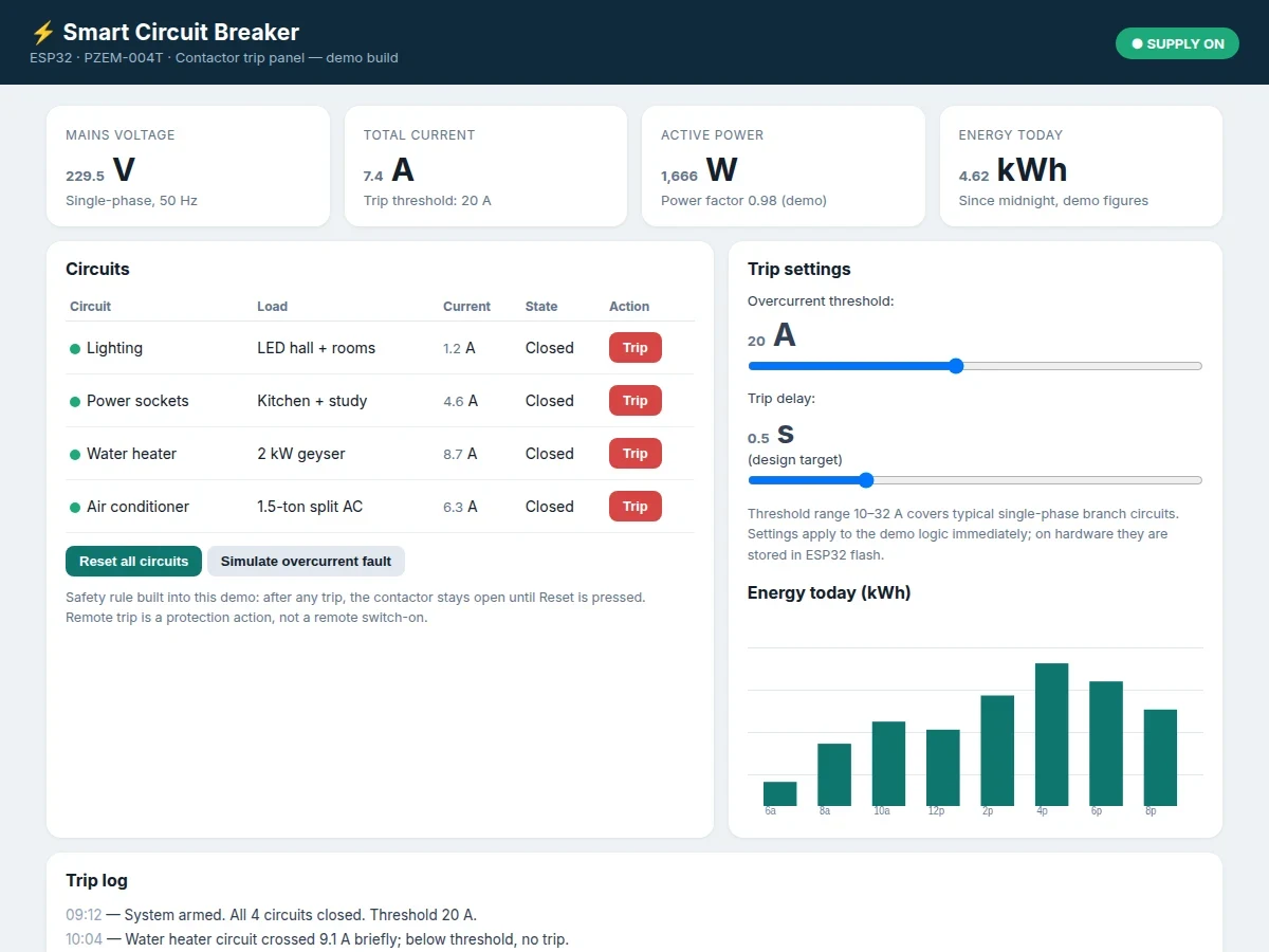
- [Live energy monitoring] (Implemented) The dashboard shows live voltage, current, active power and daily energy in kilowatt-hours, with a per-day energy chart; monitoring is a secondary function that supports protection, not the purpose of the build.
- [Local LCD and panel reset] (Implemented) A 16x2 LCD at the panel shows live voltage and current, and a physical reset button on the panel re-closes a tripped circuit without needing the dashboard.
- [Configurable thresholds] (Configurable) The overcurrent threshold is adjustable from 10 A to 32 A and the trip delay is adjustable, so the same build can protect a lighting circuit or a heavier socket circuit.
- [Trip alerts] (Optional customization) SMS or app alerts on a trip event can be added on request with a GSM module; alerts are not part of the base build and are quoted separately.
What is included
- Working hardware prototype (ESP32 panel with PZEM-004T metering, contactor trip element, LCD and reset button)
- ESP32 firmware source code (sensing, threshold logic, trip latch, trip logging)
- Working dashboard demo (live readings, circuit trip/reset, trip log, energy chart)
- Circuit diagram and wiring documentation
- Component list with ratings
- Project report PDF (background, problem, methodology, architecture, outcomes)
- PPT presentation for final review
- Viva Q&A preparation document (protection logic, sensing, contactor switching, latch safety)
Limitations & prerequisites
- This is an academic prototype, not a certified protection device: it does not replace a certified MCB or RCCB, and it must be used alongside proper certified protection, never instead of it.
- Mains wiring carries lethal voltages: the prototype must be built, tested and demonstrated under supervision, with the enclosure closed and mains terminals guarded during any demo.
- Trip accuracy depends on sensor calibration: the PZEM-004T readings should be checked against a known load during commissioning, and thresholds should be set below the circuit's certified protection rating.
- Remote trip and the dashboard need Wi-Fi: without a network, only the local LCD, the panel button and the automatic overcurrent trip keep working.
- Per-circuit current figures shown in the dashboard are demo data: the hardware reference panel meters the panel supply as a whole with one PZEM-004T module, and per-circuit metering hardware is a customization, not part of the base build.
- The trip response figure is a design target, not a measured claim: actual response depends on the contactor, the relay and the threshold settings used in the delivered build.
- Energy figures are monitoring data for a student prototype; they are not revenue-grade metering and must not be used for billing.
Timeline
- Typical built-to-order delivery: 2–3 weeks from confirmed requirements (expected, depends on customisation scope).
- Week 1: requirements freeze, panel layout and firmware sensing loop delivered as a first build.
- Week 2: trip logic, latch, dashboard and trip log completed; demo build shared for review.
- Week 3: report, PPT and viva Q&A delivered; one round of review fixes included.
Support
- Setup help over chat until the dashboard runs and the prototype trips and resets correctly on the bench.
- One round of review fixes after delivery (threshold defaults, dashboard layout, log format).
- Customisation available separately: per-circuit energy metering, GSM trip alerts, or additional branch circuits.
Frequently Asked Questions
How is this different from a smart energy meter?
A smart energy meter only measures and reports consumption, while this project is a breaker first: it physically opens a circuit on a remote command or an overcurrent fault, latches that circuit open until a deliberate reset, and logs every trip with its cause. Energy monitoring is included, but it is a secondary function that supports protection — the trip, the latch and the log are what make this a breaker rather than a meter.
Which controller and metering module are used?
The build uses an ESP32 controller with a PZEM-004T energy meter module, which reports voltage, current, active power and energy over a serial link to the controller for threshold checks and dashboard display. The ESP32 runs the threshold logic, drives the trip relay that drops the contactor, serves the dashboard over Wi-Fi, and stores the trip log. A 16x2 LCD at the panel shows live voltage and current without needing the dashboard.
Does a tripped circuit re-close on its own?
No, never: after any trip the contactor stays open until a person deliberately resets it, either from the dashboard or with the panel button, and this latch is kept separate from the Wi-Fi reconnect logic so that a dropped connection can never re-energise the circuit. That separation is a deliberate safety choice from the demo build: a dropped connection, a router restart or a power restore can never re-energise a circuit that was tripped for a fault.
Does it work without Wi-Fi?
Partly: without Wi-Fi the dashboard and remote trip are unavailable, but the automatic overcurrent trip, the local LCD readings and the panel reset button all keep working, because the protection logic runs on the ESP32 itself rather than in the cloud. The trip log keeps recording events on the controller and the dashboard shows them again once the network returns, so a Wi-Fi outage never disables protection.
Can this project be customized?
Yes, within realistic scope: common customisations are per-circuit energy metering, GSM trip alerts, more branch circuits, or a different threshold range for a heavier load, and each option is scoped and quoted separately before any work starts, so the base price stays fixed. Future-scope items such as earth-leakage detection are not claimed as included features.
Is this project suitable for a final-year project?
Yes, for Electrical Engineering and Electronics programmes, where protection, sensing and control are core topics. It demonstrates mains sensing, threshold and protection logic, contactor switching, latching safety design, event logging and a working IoT dashboard, all inside one prototype a student can trip, reset and explain live. The report, PPT and viva Q&A cover the same architecture the prototype implements.
Components & software requirements
- ESP32 microcontroller
- PZEM-004T energy meter module
- 40 A 2-pole contactor · trip relay
- Arduino IDE · ESP32 firmware
- HTML · CSS · JavaScript dashboard
- Wi-Fi · MQTT or HTTP telemetry
- 16x2 LCD local display
Hardware requirements
- ESP32 development board (dual-core, 240 MHz, datasheet value)
- PZEM-004T energy meter module with current transformer (80–260 V AC, 0–100 A, datasheet values)
- 40 A 2-pole contactor with 230 V AC coil (component rating)
- Relay module for the trip circuit
- 16x2 LCD display and panel reset push-button
- Enclosure, terminal blocks, DIN rail and mains-rated wiring
- 5 V DC supply for the controller and low-voltage electronics
Software requirements
- Arduino IDE with ESP32 board support (current stable release, design target)
- Single-file HTML/CSS/JavaScript dashboard (reference demo build included)
- Wi-Fi network for remote trip and dashboard access; local LCD works without Wi-Fi
Delivery information
Built-to-order project. Delivery timeline is shared after order confirmation based on current queue.
Support terms
Complete documentation, setup guide, and viva preparation included. Support for setup and explanation provided.
Download free synopsis (PDF)
Enter your name and WhatsApp number — the synopsis PDF downloads immediately. We may send occasional project updates on WhatsApp; no spam.