
More project photos (2)
The problem
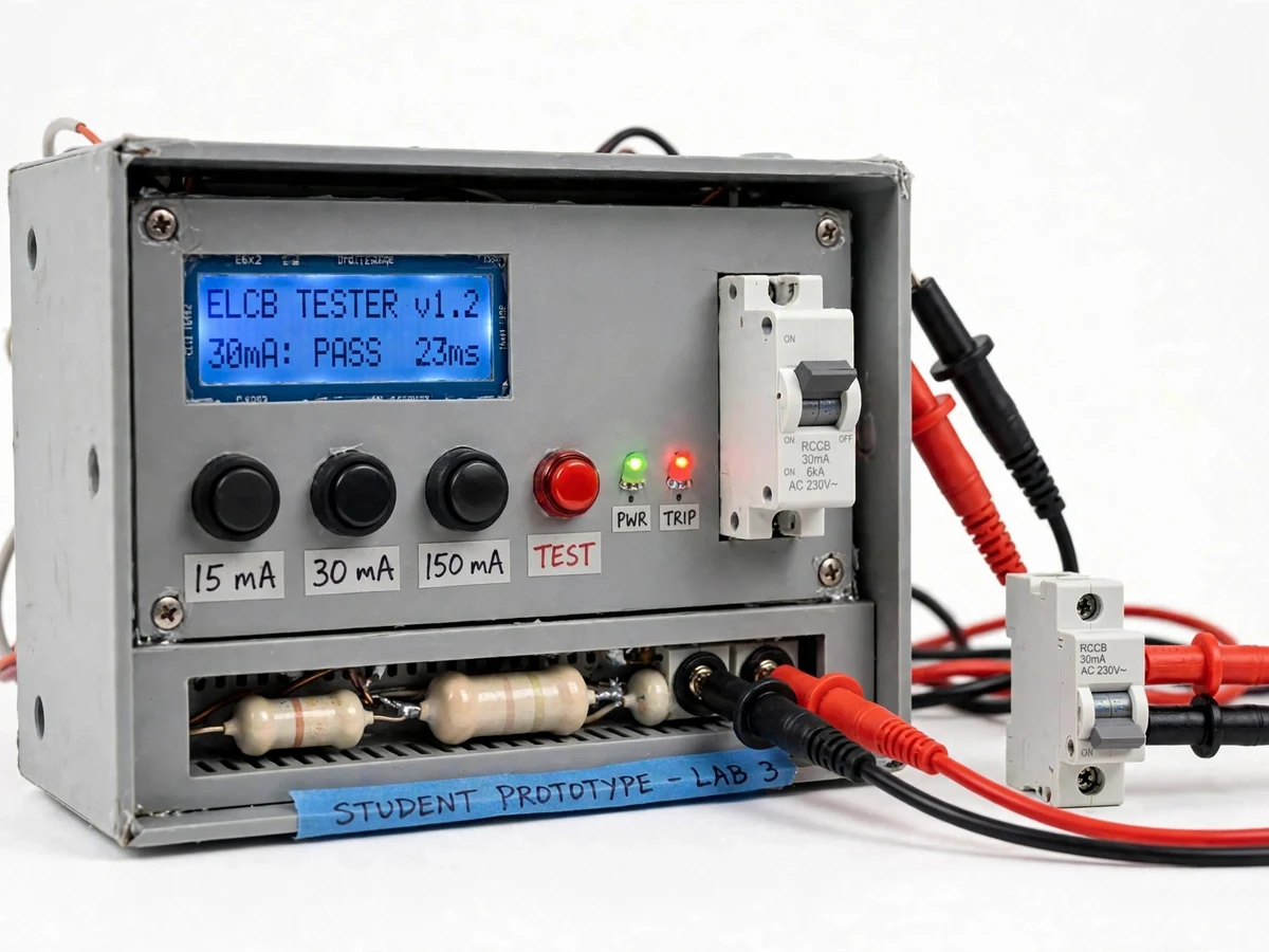
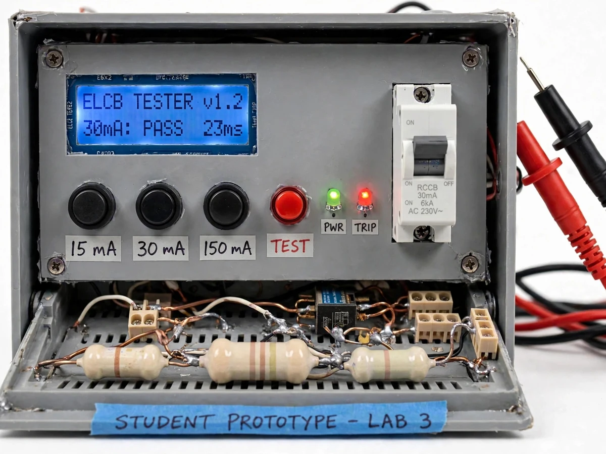
An Earth Leakage Circuit Breaker, or ELCB, protects people from electric shock when current leaks from a live conductor to earth through a faulty appliance, a damaged cable or a person. A working ELCB must trip quickly when that leakage appears, yet the breaker fitted in a home or laboratory is usually trusted without ever being tested: its test button only proves the mechanism can move, not how fast the breaker trips at a given leakage current. That gap matters, because a breaker that trips too slowly leaves the fault energised for longer than the protection was designed for. The Earth Leakage Circuit Breaker tester in this build closes that gap by injecting a known leakage current into the breaker under test, timing injection to trip, and displaying it in milliseconds on a 16x2 LCD. Push buttons select the test current, so one breaker can be checked at several leakage levels against the standard trip-time limits.
Builder note: the test currents are set by resistor values worked out from Ohm's law, not guessed. At the nominal 230 V supply, a 30 mA test current needs R = 230 ÷ 0.030 = 7,667 Ω, so a 7.5 kΩ power resistor is used, dissipating about 6.9 W while the test current flows; the 15 mA and 150 mA resistors follow the same calculation. That worked calculation is the original data in this build, and the report shows it step by step so a review panel can check it.
Selects a test current of 15, 30 or 150 mA and presses the red TEST button.
Follow the working sequence
How it works
The test runs in one chain: leakage injection, breaker trip, time measurement, display. Pressing TEST switches the selected power resistor between the live conductor and earth through a relay, so a known leakage current flows out of the live side and never returns through the neutral. Inside the ELCB, the live and neutral conductors pass through a toroidal core; equal and opposite currents cancel, so the core sees no net flux — the injected leakage current breaks that balance, the resulting flux induces a voltage in the sensing winding, and the trip mechanism releases. The breaker opens, the optocoupler sees the output voltage disappear, and the microcontroller stops the timer it started when the current was injected. The measured time in milliseconds appears on the 16x2 LCD beside the selected test current, and the green or red LED shows whether the time sits inside the standard limit for that test current.
- The tester is connected between the 230 V AC mains supply and the 30 mA ELCB or RCCB under test, the breaker is switched on, and the tester is powered up.
- A push button selects the test current — 15 mA, 30 mA or 150 mA — and the LCD shows the selected value.
- Pressing the red TEST button closes the relay, connects the selected power resistor between live and earth, injects the leakage current, and starts the microcontroller timer in the same instant.
- The injected current unbalances the toroidal core inside the breaker, the sensing winding drives the trip mechanism, and the breaker opens.
- The optocoupler senses the loss of output voltage and signals the microcontroller, which stops the timer and works out the trip time in milliseconds.
- The LCD shows the test current and the measured trip time, the green or red LED gives the pass-or-fail verdict against the standard limit, and the TEST button can be pressed again to repeat the check.
Tech stack:
- Arduino Uno · ATmega328P microcontroller
- 16x2 LCD · HD44780 display
- Test resistor bank · power resistors
- Relay · test-current switching
- Optocoupler · trip detection
- Push buttons · test-current selection
- 230 V AC mains input · fused
- Arduino IDE · Embedded C firmware
| Parameter | Value |
|---|---|
| Breaker under test | 30 mA ELCB or RCCB (design target rating) |
| Test currents | 15 mA · 30 mA · 150 mA selectable (design values) |
| Test resistor at 30 mA | 7.5 kΩ approx from 230 V ÷ 30 mA (design calculation) |
| Test resistor power at 30 mA | 6.9 W approx while current flows (design calculation) · resistor rated 10 W or higher |
| Test resistor at 15 mA | 15 kΩ approx (design calculation) · 5 W rating or higher |
| Test resistor at 150 mA | 1.5 kΩ approx (design calculation) · 50 W wire-wound resistor · current flows only until trip |
| Trip-time limit at rated current | 300 ms maximum (standard limit · IEC 61008-1) |
| Trip-time limit at 5 times rated current | 40 ms maximum (standard limit · IEC 61008-1) |
| Timer resolution | 1 ms (design target) |
| Controller | ATmega328P on Arduino Uno · 16 MHz clock (datasheet value) |
| Display | 16x2 LCD · HD44780 |
| Trip detection | Optocoupler sensing loss of output voltage |
| Switching | Relay connecting the test resistor between live and earth |
| Supply | 230 V AC mains · fused input |
| Enclosure | Insulated enclosure · shrouded test-lead plugs |
Requirements
- Arduino Uno board with ATmega328P microcontroller
- 16x2 LCD with I2C adapter
- Power resistors: 15 kΩ (5 W or higher), 7.5 kΩ (10 W or higher), 1.5 kΩ 50 W wire-wound
- Relay module for switching the test current
- Optocoupler for output-voltage sensing
- Push buttons: 3 for test-current selection, 1 red TEST button
- Green and red LEDs with series resistors
- Fuse holder with fuse for the mains input
- 30 mA ELCB or RCCB as the breaker under test
- Red and black test leads with shrouded plugs
- Insulated enclosure for the tester
- Arduino IDE for firmware upload; no internet connection is needed to use the tester
Project features
The tester's strongest capabilities are its selectable leakage currents, its millisecond trip-time measurement, its plain LCD readout, and its pass-or-fail indication against standard limits. Selectable currents let the same breaker be checked at half its rating, at its rating and at five times its rating, so the student sees how trip time falls as leakage rises instead of getting a single yes-or-no answer. The microcontroller timer turns the trip into a number in milliseconds, which is the quantity a review panel actually wants to see. The 16x2 LCD always shows the selected test current beside the measured trip time, so a result is never ambiguous and never needs a separate meter to read. The pass-or-fail LEDs compare that measured time with the standard limits for the rating under test, so the verdict is visible the moment the breaker trips, and the repeat-test button lets the same check run again without rewiring anything.
- [Selectable leakage test currents] (Implemented) Three push buttons select test currents of 15 mA, 30 mA and 150 mA — half, one and five times the 30 mA rating of the breaker under test — so one breaker can be checked at three leakage levels without changing any wiring.
- [Millisecond trip-time measurement] (Implemented) A microcontroller timer starts in the same instant the test current is injected and stops the moment the breaker trips, giving the trip time in milliseconds with a 1 ms timer resolution (design target).
- [LCD readout of current and trip time] (Implemented) A 16x2 LCD shows the selected test current beside the measured trip time, so every result is readable on the unit itself with no separate meter.
- [Pass-or-fail indication] (Implemented) Green and red LEDs compare the measured trip time with the standard limits for the rating under test — 300 ms maximum at rated current and 40 ms maximum at five times rated current (standard limits, IEC 61008-1) — so the verdict is visible as soon as the breaker trips.
- [Trip detection through output-voltage sensing] (Implemented) An optocoupler watches the output side of the breaker under test and signals the microcontroller the instant the output voltage disappears, so the timer stops on the real trip and not on a guessed delay.
- [Fused input and insulated enclosure] (Implemented) The mains input passes through a fuse, the live parts sit inside an insulated enclosure, and the test leads use shrouded plugs, so the tester is handled as the live-mains instrument it is.
- [Repeat test without rewiring] (Implemented) Pressing the red TEST button again re-runs the same check, so a result can be confirmed with a second run before it is written down.
- [Serial test log] (Optional) A serial output of the test current and trip time for each run can be added on request, so results can be saved on a laptop instead of copied from the display by hand.
What is included
- Working ELCB tester prototype in an insulated enclosure with LCD, push buttons, relay, resistor bank and test leads
- Complete firmware source code (Arduino IDE, Embedded C) with the timer and pass-or-fail logic
- Circuit diagram and wiring documentation
- Resistor selection calculations shown step by step from Ohm's law
- Test procedure for all 3 test currents with the standard trip-time limits
- Project abstract PDF
- Project report (ELCB working principle, core-balance mechanism, resistor design, firmware logic, test procedure, limitations)
- PPT presentation for final review
- Viva Q&A preparation document (ELCB core balance, Ohm's-law resistor design, trip-time limits, mains safety)
- Demonstration guidance for the viva
Timeline
- Week 1: design and component selection — test currents, resistor values from Ohm's law, trip-time limits, with the circuit diagram drawn and checked.
- Week 2: enclosure build and firmware — LCD, push buttons, relay and optocoupler wired and coded, with the timer tested on the bench.
- Week 3: integration and testing — resistor bank, trip detection and pass-or-fail indication combined, with the breaker tested at all 3 currents.
- Week 4: documentation and demo — report, abstract, PPT and viva Q&A prepared, with a rehearsed demonstration of the full test sequence.
Support
- Build guidance and doubt-clearing during the project period, with the firmware, resistor calculations and test procedure explained step by step.
- Documentation support: report, abstract, PPT and Q&A are prepared to match the delivered build, and corrections are made if the college format needs a change.
- Customization on request: a serial test log, test currents for other breaker ratings, or an OLED display can be added based on technical feasibility and timeline.
- Request a quotation on WhatsApp with your branch, college deadline and any required customization — the scope, price and delivery date are confirmed before the build starts.
Limitations & prerequisites
- Live-mains instrument: the tester works on live 230 V AC mains and is a test instrument for qualified use under supervision; it is an academic prototype, not a certified commercial test instrument, and it must never be presented as one.
- Results depend on supply voltage: the test current follows Ohm's law from the actual mains voltage, so a supply that is not at the nominal 230 V shifts the injected current from the design value.
- Indicative timing, not calibration-grade: the trip time is measured by the built instrument with a 1 ms timer resolution (design target); it is not a calibrated measurement and cannot be quoted as a certification result.
- Brief high-current injection: at the 150 mA test current the resistor dissipates about 34.5 W (design calculation), so the current flows only until the breaker trips and the test must not be held on.
- One breaker rating in the base build: the test currents and pass-or-fail limits are set for a 30 mA breaker; other ratings need different resistor values and are a customization.
- No earth-loop or insulation test: the tester measures ELCB trip time only; it does not measure earth-loop impedance or insulation resistance, which need separate instruments.
Frequently Asked Questions
Is this project suitable for a final-year project?
Yes. It fits final-year work in Electrical Engineering because it combines protection theory, Ohm's-law design, embedded timing and live-mains test practice in one working instrument. The student can explain the core-balance mechanism, show the resistor calculation, and defend a measured trip time against a standard limit, which is exactly the depth a review panel looks for.
How does the tester measure trip time?
The microcontroller starts a timer in the same instant the relay injects the test current, and an optocoupler watches the output side of the breaker under test. When the breaker trips, the output voltage disappears, the optocoupler signals the microcontroller, and the timer stops. The difference is the trip time, shown in milliseconds on the 16x2 LCD.
How are the test resistor values chosen?
Each value comes from Ohm's law at the nominal 230 V supply. For a 30 mA test current, R = 230 ÷ 0.030 = 7,667 Ω, so a 7.5 kΩ power resistor is used, dissipating about 6.9 W while the current flows. The 15 mA and 150 mA resistors follow the same calculation, and the report shows every step so the values can be checked.
Is it safe to use on live mains?
The tester works on live 230 V AC mains, so it is used only under qualified supervision, with the fused input, insulated enclosure and shrouded test leads fitted as designed. It is an academic prototype and a test instrument for learning, not a certified commercial tester, and it must never be used on a live installation without supervision.
What counts as a pass or a fail?
A pass means the breaker tripped within the standard limit for the test current: 300 ms maximum at the rated 30 mA current, and 40 ms maximum at five times the rating, 150 mA (standard limits, IEC 61008-1). The green LED lights for a pass and the red LED for a fail, and the LCD shows the measured time so the verdict can be checked.
Can the tester check breakers of other ratings?
The base build is set for a 30 mA breaker, with test currents of 15 mA, 30 mA and 150 mA and limits matched to that rating. Breakers of other ratings can be supported by changing the resistor values and the pass-or-fail limits, which is offered as a customization; the scope, price and delivery date are confirmed on WhatsApp before the build starts.
Components & software requirements
- Arduino Uno · ATmega328P microcontroller
- 16x2 LCD · HD44780 display
- Test resistor bank · power resistors
- Relay · test-current switching
- Optocoupler · trip detection
- Push buttons · test-current selection
- 230 V AC mains input · fused
- Arduino IDE · Embedded C firmware
Delivery information
Built-to-order project. Delivery timeline is shared after order confirmation based on current queue.
Support terms
Complete documentation, setup guide, and viva preparation included. Support for setup and explanation provided.
Download free synopsis (PDF)
Enter your name and WhatsApp number — the synopsis PDF downloads immediately. We may send occasional project updates on WhatsApp; no spam.