
More project photos (3)
The problem
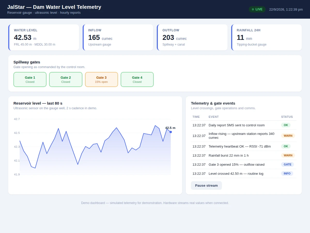
Dam operators make release decisions from water-level data, and in many small reservoirs that data still arrives by phone from a gauge reader once a day. The engineering gap is a low-cost telemetry unit that watches the level continuously, reports on schedule, and raises the alarm before the water reaches the danger mark — not after. This project builds that unit on an ESP32: an HC-SR04 ultrasonic sensor mounted over a gauge well measures the level without touching the water, the firmware converts distance to reservoir level against a calibrated datum, and readings stream to a dashboard with level curves, gate status, inflow/outflow entries and configurable alert thresholds. A model dam with a water reservoir demonstrates the full loop on the bench.
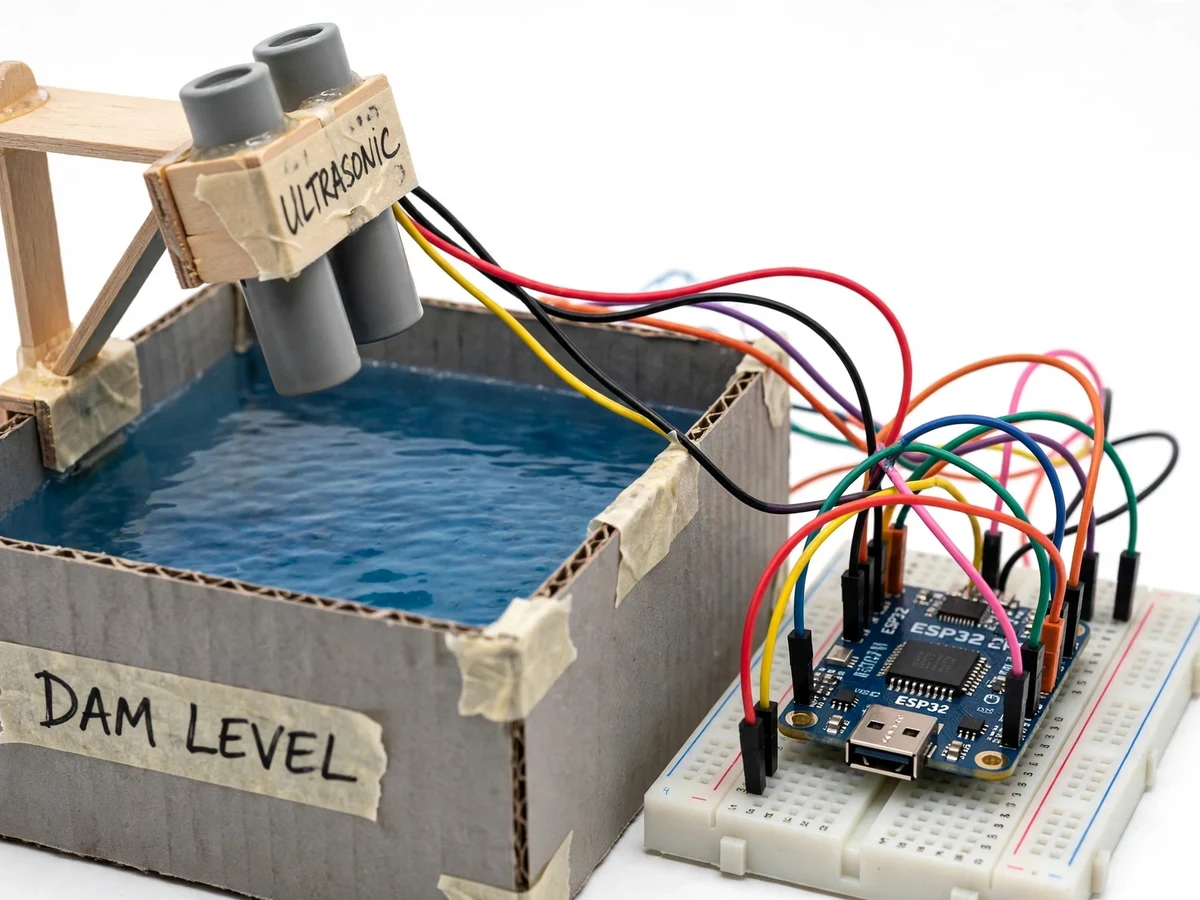
Ultrasonic sensor fires at the water surface in the gauge well; the echo time gives distance.
Follow the working sequence
How it works
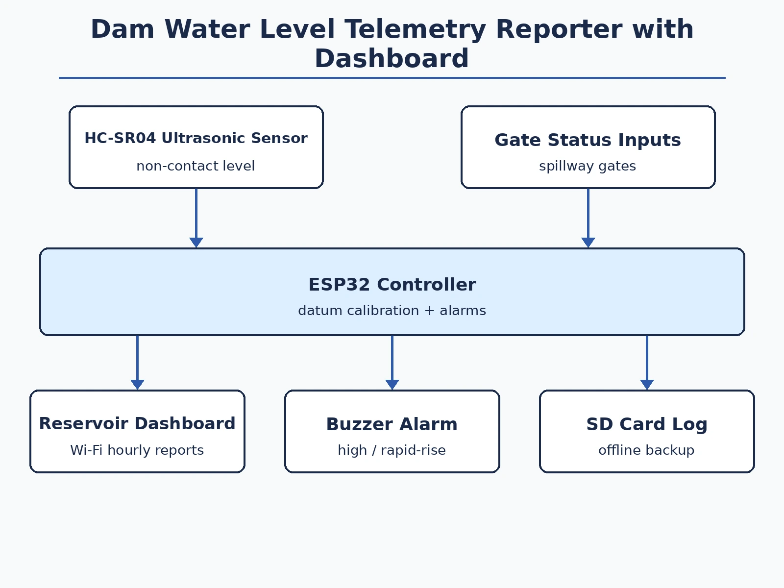
- The ultrasonic sensor fires at the water surface in the gauge well and the ESP32 times the echo to get distance.
- Firmware subtracts the distance from the calibrated datum height to produce reservoir level in metres.
- A moving median filter rejects ripples and stray echoes before the value is accepted.
- Accepted readings publish to the dashboard every few seconds; a compact hourly summary is stored for the daily report.
- If the level crosses a threshold or rises faster than the configured rate, the alarm path fires locally and on the dashboard.
- Gate positions and flow entries are logged alongside, giving the operator one screen for level, releases and trend.
Tech stack:
- ESP32 development board (Wi-Fi telemetry)
- HC-SR04 ultrasonic distance sensor
- Real-time clock module (timestamped logging)
- MicroSD card module (backup log)
- Buzzer + status LEDs (local alarms)
- Model dam with reservoir (demonstration rig)
- Single-page reservoir dashboard (HTML/JS)
| Parameter | Value |
|---|---|
| Controller | ESP32, Wi-Fi telemetry to dashboard |
| Level sensor | HC-SR04 ultrasonic; 2–400 cm range per datasheet |
| Measurement | Non-contact, from gauge-well bracket; datum set at installation |
| Filtering | Moving median over 5 samples (firmware) |
| Reporting | Live stream + hourly summary; SD backup log |
| Alarms | High level, rapid rise, sensor fault — local buzzer + dashboard flag |
| Dashboard | Level curve, gate panel, inflow/outflow log, alert history |
| Power | 5 V USB / battery pack for field-style deployment |
Project features
- [Non-contact level sensing] The ultrasonic sensor measures the water surface from above, so there is nothing to corrode, foul or submerge.
- [Datum-calibrated readings] Firmware converts raw distance to reservoir level against a surveyed datum the student sets during installation — the report documents the calibration.
- [Hourly reporting] The unit publishes a scheduled report (level, trend, gate state) to the dashboard and can log to an SD card as backup.
- [Threshold alerts] High-level, rapid-rise and sensor-fault alarms trigger the buzzer locally and flag the dashboard immediately.
- [Gate status panel] Spillway gate positions are entered or sensed and shown alongside the level, so release decisions read in context.
- [Inflow/outflow log] Manual or sensor-fed flow entries sit next to the level curve, making the water-balance story visible.
- [Offline buffering] Readings timestamp on-device and sync when connectivity returns, so a network gap never loses the record.
What is included
- Working telemetry prototype (ultrasonic sensor, ESP32, RTC, SD logging, alarm buzzer)
- Model dam with reservoir for bench demonstration
- Complete firmware source code (sensing, filtering, calibration, reporting, alarms)
- Reservoir dashboard with level curves and alert log
- Circuit and wiring documentation
- Datum calibration procedure (the buyer's own setup run, documented in the report)
- Project report PDF (hydrometry basics, calibration, logged data from the buyer's run)
- PPT presentation for final review
- Viva Q&A preparation document (ultrasonic ranging, datum, telemetry design, alarm logic)
Limitations & prerequisites
- Demonstrated on a model reservoir; a real dam deployment would need weatherproofing, lightning protection and a proper stilling well — all listed as future scope.
- Ultrasonic readings are affected by surface turbulence and temperature; the firmware filters but cannot remove all noise.
- Inflow/outflow values in the demo are entered or simulated — the unit measures level, not discharge.
- Alert thresholds are set by the operator; the project provides the mechanism, not the hydrology judgment.
- Wi-Fi range limits the live dashboard; the SD log is the reliable record in the field.
Frequently Asked Questions
How does it measure the level without touching water?
An ultrasonic sensor mounted above the gauge well times the echo off the water surface; the firmware subtracts that distance from a calibrated datum height to get the reservoir level.
What is the datum calibration?
The student measures the sensor height above a known reference mark once at installation and stores it in firmware — every later reading is level above that datum. The report documents the procedure.
How does it handle waves and ripples?
A moving median filter over five samples rejects most ripple noise before a reading is accepted or alarmed on.
What happens when the network drops?
Readings keep timestamping to the SD card on-device and sync to the dashboard when connectivity returns.
Can it open the spillway gates itself?
No — the panel shows gate positions for context, but gate actuation stays manual. Automatic gate control is listed as future scope.
Is this project suitable for a final-year project?
Yes — for Electronics, Electrical and IoT & Embedded programs. It is real instrumentation: non-contact sensing, calibration, telemetry and alarm logic around civil infrastructure. Suitable for B.E./B.Tech final-year projects in Electronics, Electrical and IoT & Embedded Systems.
Components & software requirements
- ESP32 development board (Wi-Fi telemetry)
- HC-SR04 ultrasonic distance sensor
- Real-time clock module (timestamped logging)
- MicroSD card module (backup log)
- Buzzer + status LEDs (local alarms)
- Model dam with reservoir (demonstration rig)
- Single-page reservoir dashboard (HTML/JS)
Delivery information
Built-to-order project. Delivery timeline is shared after order confirmation based on current queue.
Support terms
Complete documentation, setup guide, and viva preparation included. Support for setup and explanation provided.
Download free synopsis (PDF)
Enter your name and WhatsApp number — the synopsis PDF downloads immediately. We may send occasional project updates on WhatsApp; no spam.