
More project photos (2)
The problem
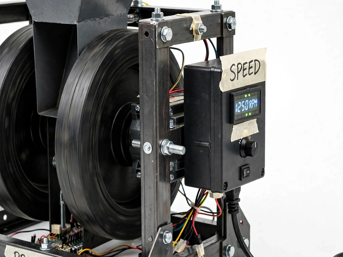
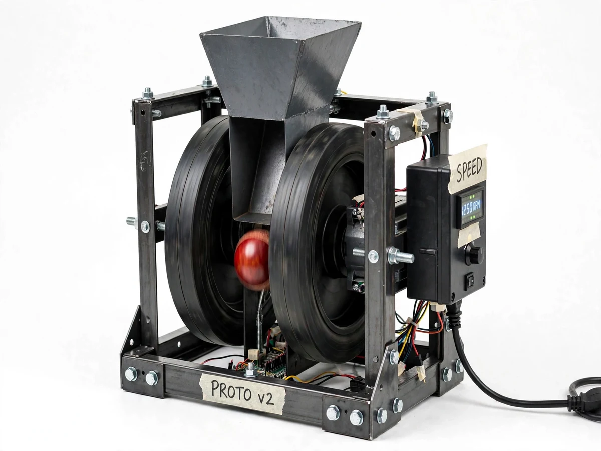
A cricket bowling machine with adjustable speed and swing fires cricket balls at a batsman using two spinning rubber wheels on an adjustable frame. The machine uses twin counter-rotating wheels driven by 24 V DC motors: a ball dropped through the top hopper is squeezed between the wheels and launched at the panel-set speed. Amateur cricketers rarely get a steady, repeatable feed of deliveries: human throw-downs vary in pace and line, while commercial machines are expensive and need trained operators. A student-scale machine closes that gap — it gives nets a repeatable practice tool built from common motors, steel angle and rubber wheels at a fraction of commercial cost. Swing comes from a speed difference between the two wheels: the faster wheel drags one side of the ball harder, rolling spin onto it, and the spinning seam separates airflow asymmetrically — the Magnus effect, the same physics that bends a swing bowler's delivery.
Sets the delivery speed on the control panel knob and feeds balls into the hopper.
Follow the working sequence
How it works
The Cricket Bowling Machine turns two spinning wheels into a repeatable bowling action. The operator selects a delivery speed on the control-panel knob, and the PWM controller drives both DC motors to the corresponding wheel RPM, shown live on the digital display. A cricket ball dropped into the top hopper rolls down the feed chute and lands in the gap between the two counter-rotating wheels, spaced slightly narrower than the ball so the rubber grips and compresses it on contact. Friction accelerates the ball in a fraction of a second, and it exits the delivery tube toward the batsman at the target speed. For swing, differential mode spins one wheel slightly faster: the faster surface drags one side of the ball, rolling spin onto it, and the spinning seam separates airflow asymmetrically to curve the flight — the Magnus effect. The operator then shifts line and length by tilting or swiveling the head mount and feeds the next ball.
- The operator sets the delivery speed on the control-panel knob; the PWM controller drives both DC motors to the matching wheel RPM shown on the display.
- A cricket ball is placed in the top hopper and rolls down the feed chute into the pinch point between the two counter-rotating wheels.
- The wheel gap — set 10–15 mm narrower than the ball diameter (see builder note below) — lets the rubber grip and compress the ball momentarily.
- Friction accelerates the ball through the contact zone and launches it down the delivery tube toward the batsman.
- For swing, differential mode runs one wheel slightly faster, spinning the ball so its seam curves the flight through the air.
- Line and length are adjusted by tilting or swiveling the head mount, and the next ball is fed for the following delivery.
Builder note from the build process: set the wheel gap 10–15 mm narrower than the ball diameter. Test it with the power off by pressing a ball through by hand — it should need a firm push without jamming. Too tight stalls the motors; too loose and the ball slips through with low speed.
Tech stack:
- 24 V DC motors (775-class) × 2
- PWM motor speed controller
- Mild-steel angle frame (bolted)
- Rubber throwing wheels (approximately 250 mm)
- Digital RPM display (tachometer)
- Sheet-metal ball hopper and feed chute
- Emergency-stop switch and wheel guards
- 24 V SMPS power supply (230 V AC mains)
| Parameter | Value |
|---|---|
| Drive motors | 2 × 24 V DC motors, 775-class frame, wheel speed PWM-limited to 800–3000 RPM (operating range, design target) |
| Wheel speed range | 800–3000 RPM (design target, panel-adjustable) |
| Ball speed | 60–100 km/h (design target, speed-setting dependent) |
| Theoretical no-slip maximum | Approximately 141 km/h at 3000 RPM (calculated from wheel size and RPM, not measured) |
| Throwing wheels | 2 × rubber wheels, approximately 250 mm diameter |
| Wheel gap | 10–15 mm narrower than ball diameter (builder-set at assembly) |
| Feed method | Gravity hopper with top-feed chute |
| Power supply | 24 V DC SMPS, runs on 230 V AC mains |
| Frame | Mild-steel angle, bolted construction |
| Control | Panel knob + PWM controller with digital RPM display |
| Ball type | Standard leather cricket ball, approximately 156 g |
Project features
The Cricket Bowling Machine combines four capabilities for the practice net. Adjustable speed control lets the operator dial the delivery pace from gentle throw-downs to brisk seam-up pace through a panel knob driving both DC motors with PWM control, so beginners and experienced batsmen share one machine. Swing generation runs the two wheels at slightly different speeds, rolling spin onto the ball so the seam position curves its flight through the air — genuine swing aerodynamics rather than a straight throw. Repeatable delivery mechanics mean every ball leaves the wheels from the same point with the same energy once set: the hopper feeds ball after ball while the rigid steel frame holds wheel alignment, making practice sessions measurable. Finally, the adjustable head mount changes tilt and swivel, shifting line and length without dragging the whole machine around. An RPM display, the gravity-feed hopper and safety guarding support these four in the base build.
- [Adjustable speed control] A panel knob drives a PWM motor controller that sets both DC motors together, with wheel speed adjustable from approximately 800 to 3000 RPM (design target) — slow throw-downs to brisk pace from one machine.
- [Swing generation] A differential-speed mode runs the two wheels at slightly different rates, rolling spin onto the ball so the seam curves its flight through the air via the Magnus effect.
- [Adjustable head angle] The machine head tilts and swivels on its mount, changing the delivery's line and length without moving the frame.
- [Top-feed ball hopper] A sheet-metal hopper holds several balls and gravity-feeds them one at a time down the chute into the wheel gap.
- [RPM display] A digital tachometer on the control panel shows live wheel RPM so the operator can repeat exact speed settings between sessions.
- [Steel frame chassis] A rigid mild-steel angle frame holds the motors, wheels and head mount in alignment under the vibration of spinning wheels.
- [Safety guarding] Wheel guards cover the spinning wheels and a panel-mounted emergency-stop switch cuts motor power instantly.
Implemented in the base build: all seven features above. Optional customizations (quoted separately): battery-pack operation, automatic ball magazine, remote speed control. Future scope: radar speed readout, spin-axis camera analysis.
What is included
- Fabricated cricket bowling machine prototype (wheels, frame, hopper, control panel with RPM display)
- Wired motor speed controller, emergency-stop switch and wheel guards
- Build documentation: component list, wiring diagram, fabrication drawings
- Operating and calibration manual (wheel-gap setting procedure, speed calibration steps)
- Project report PDF (design rationale, fabrication process, testing observations)
- PPT presentation for final review
- Viva Q&A preparation document
Limitations & prerequisites
- The 60–100 km/h ball-speed figure is a design target, not a measured claim — final speed depends on wheel condition, ball grip and motor loading, and is verified with radar or video timing at delivery.
- Swing depends on seam position and ball condition: a new ball with a raised seam curves far more than a worn smooth one, so swing varies ball to ball.
- Wheel-gap calibration is manual — set too tight the motors stall, too loose and the ball slips through with low speed; the operating manual documents the trial procedure.
- The machine is mains-powered and heavy (frame plus motors, approximately 25–30 kg expected), so it is not portable for casual travel.
- Delivery line and length depend on consistent ball feeding; hurried feeding shifts the release point and scatters deliveries.
- Rubber wheels wear with use and need periodic replacement — worn wheels lose grip and ball speed drops.
- This is a practice aid, not a match-play device: it cannot replicate a bowler's action, release variation or tactical changes in a spell.
Frequently Asked Questions
Is this project suitable for a final-year project?
Yes — for Mechanical and Electrical/Electronics branches. It covers machine design, friction-drive power transmission, DC motor speed control, steel fabrication and hands-on calibration and testing. The report explains the design rationale and test observations, and the PPT plus Q&A kit prepare the viva.
How does the machine produce swing?
By running the two wheels at slightly different speeds: the faster wheel drags one side of the ball harder, rolling spin onto it, and the spinning seam makes the airflow asymmetric so the ball curves — the Magnus effect, the same physics behind swing bowling. Seam position at release still matters, so swing varies.
What speed range can it bowl?
The design target is 60–100 km/h, set by the panel knob through a wheel RPM range of approximately 800–3000. Final ball speed is verified at delivery with a radar or frame-timed video test, since wheel wear and ball condition affect the number.
What power supply does it need?
A 24 V DC SMPS running from standard 230 V AC mains; the machine ships fully wired with an emergency-stop switch, and the mains input is fused with high-voltage wiring enclosed in the panel. A battery-pack option for outdoor nets without mains access is available as an optional customization.
Can it be customized?
Realistic options include an automatic ball magazine, battery operation, remote speed control, or a smaller wheel set for tennis-ball practice. Each is quoted separately based on technical feasibility and timeline, since they are not part of the base build. Wheel-size or hopper changes are feasible; frame geometry changes need a fresh design review.
What will I receive with the project?
The working prototype, wiring and fabrication documentation, the operating and calibration manual, the project report PDF, the PPT presentation and the viva Q&A document. Everything is built and documented fresh for your order. Fabrication drawings are included so the build can be explained confidently in the viva.
Components & software requirements
- 24 V DC motors (775-class) × 2
- PWM motor speed controller
- Mild-steel angle frame (bolted)
- Rubber throwing wheels (approximately 250 mm)
- Digital RPM display (tachometer)
- Sheet-metal ball hopper and feed chute
- Emergency-stop switch and wheel guards
- 24 V SMPS power supply (230 V AC mains)
Delivery information
Built-to-order project. Delivery timeline is shared after order confirmation based on current queue.
Support terms
Complete documentation, setup guide, and viva preparation included. Support for setup and explanation provided.
Download free synopsis (PDF)
Enter your name and WhatsApp number — the synopsis PDF downloads immediately. We may send occasional project updates on WhatsApp; no spam.