
More project photos (2)
The problem
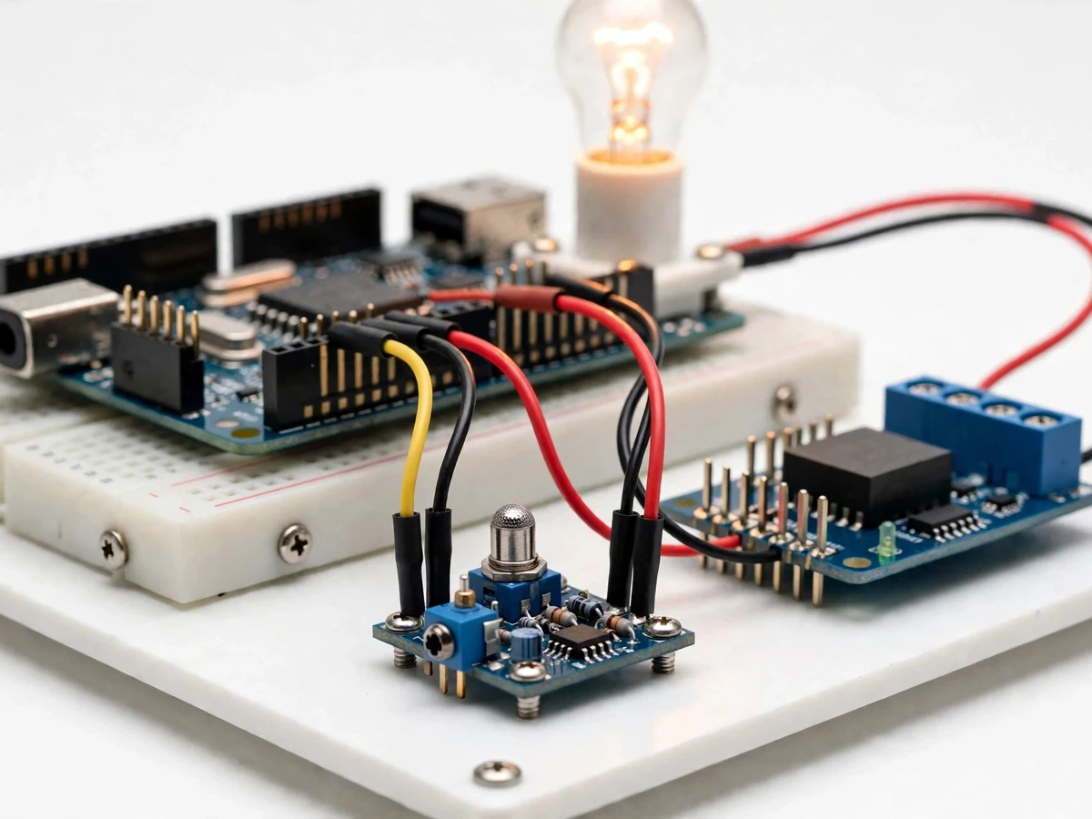
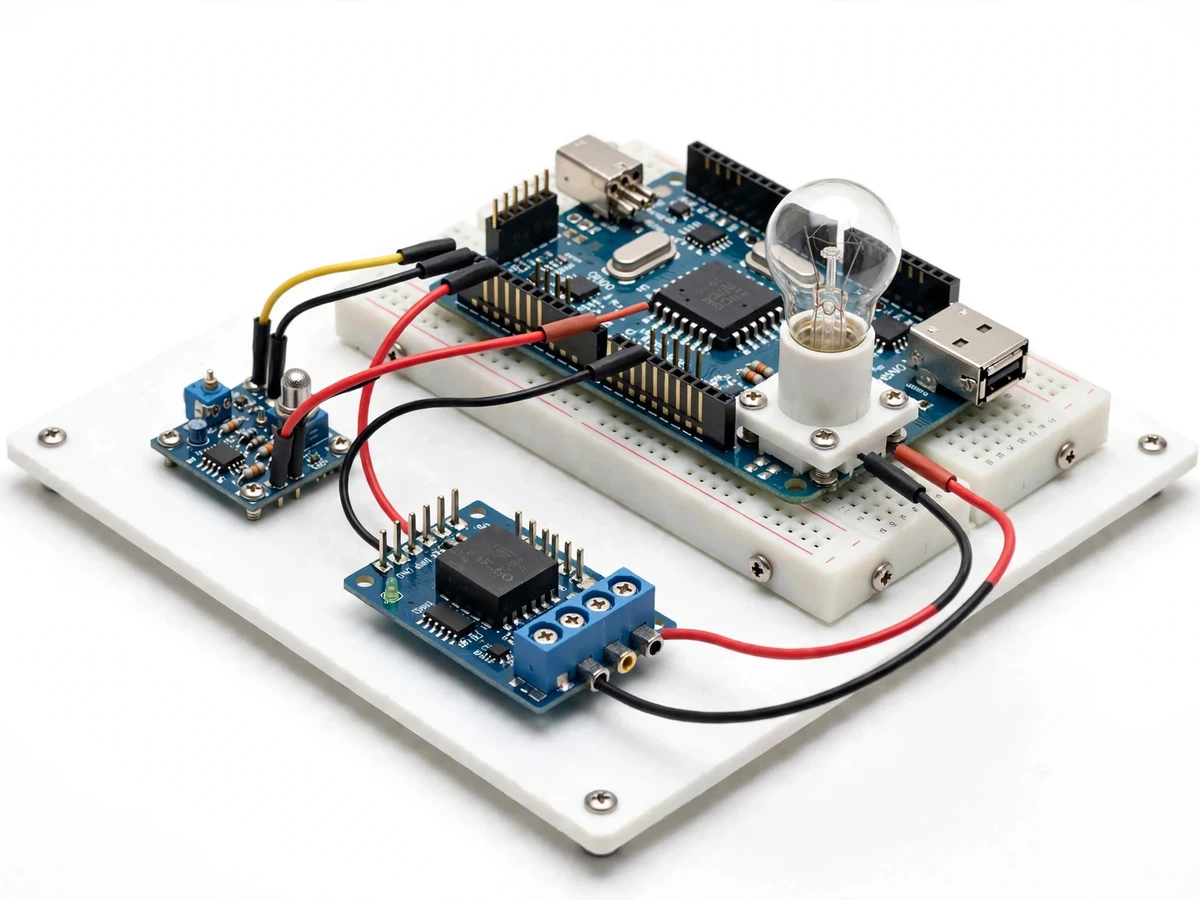
Clap Switch using Sound Sensor and Arduino is a hands-free switching prototype that turns a lamp on or off when a person claps twice. A sound sensor module listens for sharp sounds, an Arduino Uno judges whether the sounds form the expected double-clap pattern, and a relay module switches the lamp circuit in response. The build is deliberately small: one controller, one sensor, one relay and one lamp, so every stage from sound to switching can be traced on a single board. It suits rooms where reaching a wall switch is awkward, such as beside a bed or a workbench, and it demonstrates the core embedded ideas of sensing, threshold comparison, timing logic and electrically isolated switching. Because the lamp is switched through a relay, the low-voltage control side stays separate from the mains side, which is itself an important design lesson for any student working with mains-powered loads.
Many everyday switches assume the user can always reach them, which is not true in the dark, from bed, or with hands full. Voice assistants solve this with a network connection and a microphone that is always listening, but that is a heavy answer for a single lamp. A clap switch is the minimal version of the same idea: a sharp, deliberate sound becomes the command, no network is needed, and the whole decision chain fits on one microcontroller. The engineering interest is not the clap itself but the judgement around it — telling a real double clap apart from a dropped book, a door slam or normal conversation — which is where threshold tuning and timing windows come in.
Electret microphone plus LM393 comparator turns a loud sound into a digital pulse.
Follow the working sequence
How it works
Clap Switch using Sound Sensor and Arduino works as a short chain from sound to switching: sound reaches the sensor, the sensor turns it into a signal, the Arduino judges the pattern, and the relay acts. A clap strikes the sensor module's electret microphone, which converts the sharp sound into a small electrical signal; the module's comparator compares that signal with the potentiometer-set threshold and outputs a digital pulse for every sound loud enough to cross it. The Arduino watches for these pulses and counts them: a first pulse starts a short detection window, and only if a second pulse arrives inside that window does the firmware treat the pair as a command. It then flips the relay, the relay contacts close or open, and the lamp turns on or off accordingly, while a brief blanking interval stops the relay's own click from being counted as another clap.
- The sound sensor module's electret microphone picks up room sound and converts it into an electrical signal.
- The module's LM393 comparator compares the signal with the threshold set by the onboard potentiometer and outputs a digital pulse for each sound above that threshold.
- The Arduino reads the digital pulse on a digital input pin and timestamps it.
- The first accepted pulse starts the detection window (design target: approximately 1.5 s); a second pulse inside the window is treated as a double clap, while a lone pulse is discarded when the window expires.
- On a confirmed double clap, the firmware flips the relay output pin, toggling the relay module and the lamp state.
- After toggling, the firmware blanks sensor input for a short interval (design target: approximately 0.5 s) so the mechanical click of the relay is not counted as a new clap, then resumes listening.
Builder note from the build: the tuning step that makes the difference is setting the threshold in the actual room, not on the bench alone. Turn the sensitivity potentiometer until the module's onboard indicator just stops flickering in a quiet room, then clap once and check that the indicator flashes once per clap; if ordinary speech triggers it, back the potentiometer off a quarter-turn and test again. The second practical lesson is placement: keep the sensor module away from the relay itself, because the relay's click is loud enough at close range to retrigger an untuned build.
Tech stack:
- Arduino Uno (ATmega328P)
- LM393 sound sensor module
- Single-channel 5 V relay module
- Arduino IDE (C/C++ firmware)
- Breadboard · jumper wires · push button
- 230 V AC demonstration lamp with enclosed holder
- 5 V USB power supply
- Solderless prototype base board
| Parameter | Value |
|---|---|
| Controller | Arduino Uno, ATmega328P (datasheet value) |
| Operating voltage | 5 V (datasheet value) |
| Digital I/O pins | 14 pins (datasheet value) |
| Analog inputs | 6 pins, 10-bit ADC resolution (datasheet value) |
| Recommended input voltage | 7–12 V DC (datasheet value) |
| Sound sensor | LM393 comparator module with electret microphone (datasheet value) |
| Sensor supply | 3.3–5 V (datasheet value) |
| Sensor outputs | Digital output (DO) and analog output (AO) (datasheet value) |
| Sensitivity adjustment | Onboard potentiometer (adjustable, no fixed value) |
| Relay module | Single-channel, 5 V coil (datasheet value) |
| Relay contact rating | 10 A at 250 V AC (datasheet value) |
| Demonstration load | 230 V AC lamp in an enclosed holder (design target) |
| Clap pattern | 2 claps (design target) |
| Detection window | Approximately 1.5 s (design target) |
| Post-toggle blanking | Approximately 0.5 s (design target) |
| Connectivity | None required — fully offline (design target) |
Project features
Clap Switch using Sound Sensor and Arduino gives a student four capabilities to demonstrate: double-clap toggle control, adjustable sound sensitivity, false-trigger filtering, and relay-isolated lamp switching. The double-clap toggle is the headline behaviour — two claps switch the lamp, and two more switch it back — while adjustable sensitivity lets the same build be tuned for a quiet bedroom or a noisier living room. False-trigger filtering is what makes the switch usable rather than a novelty: the firmware only accepts claps that arrive as a pair inside a short window, and it ignores the relay's own click after switching. Relay isolation keeps the 5 V control circuit electrically separate from the lamp circuit, and a status LED plus a manual push-button override complete a build that is practical to demonstrate and easy to explain.
- [Double-clap toggle control] [Implemented] Two claps within the detection window toggle the lamp state; two more claps toggle it back. The lamp holds its state between commands, so no continuous sound is needed.
- [Adjustable sound sensitivity] [Implemented] The sensor module's onboard potentiometer sets the sound level that counts as a clap, so the build can be tuned for a quiet room or a noisier space without changing code.
- [False-trigger filtering] [Implemented] The firmware accepts only a pair of sharp pulses inside the detection window and blanks out input briefly after each relay toggle, so the relay's own click cannot retrigger the switch.
- [Relay-isolated lamp switching] [Implemented] A single-channel relay module switches the lamp circuit while keeping the 5 V Arduino side electrically separate from the lamp side.
- [Status LED indication] [Implemented] An LED on the board shows the current lamp state and flashes on each accepted clap, so the audience can follow the decision even when the lamp is out of view.
- [Manual push-button override] [Implemented] A push button toggles the lamp directly, giving a fallback if the room is too noisy for clap control and a simple way to test the relay on its own.
- [Configurable clap pattern and window] [Configurable] The required clap count and the detection window are constants in the firmware, so a student can change the build to a single-clap or triple-clap command and document the trade-off.
What is included
- Working clap-switch prototype (Arduino, sound sensor module, relay module, lamp and base board)
- Arduino firmware source code with commented threshold, window and blanking constants
- Wiring diagram and component list
- Threshold-tuning procedure for the student's own room
- Project report PDF (background, sensor and relay theory, methodology, testing procedure)
- PPT presentation for final review
- Viva Q&A preparation document (comparator thresholds, timing logic, relay isolation, mains safety)
- Demonstration guidance for the viva table
Timeline
- Week 1: Component assembly, wiring and first power-on checks.
- Week 2: Firmware, threshold tuning and double-clap logic testing in the demo room.
- Week 3: Final assembly on the base board, report and PPT preparation.
- Week 4: Delivery with demonstration guidance and viva Q&A walkthrough.
Support
- Setup guidance for wiring the prototype and tuning the threshold in the student's room.
- Explanation support for the report, PPT and viva Q&A before the final review.
- Guidance on safe handling of the mains-side lamp wiring during demonstrations.
Limitations & prerequisites
- The switch responds to any sufficiently loud sharp sound, not to a specific person's clap — it cannot identify who clapped.
- Very noisy rooms (television at high volume, a nearby mixer grinder, a party) can cause false triggers; the threshold must be retuned for each room.
- The sensor cannot measure loudness in decibels or recognise speech; it only reports whether sound crossed a set threshold.
- The detection window and blanking interval are design targets (approximately 1.5 s and approximately 0.5 s); they are not measured response-time claims and vary with room acoustics.
- The demonstration lamp runs on mains voltage, so the lamp wiring must stay inside its enclosed holder and must not be rewired by the student without supervision.
- The prototype is an academic demonstration build, not a certified home-automation product, and it has no remote control, scheduling or app.
- Clap detection range depends on room size, furnishings and background noise, so no fixed detection distance is claimed.
Future scope (not included in the base build)
- A second relay channel so one clap pattern controls a lamp and another controls a fan.
- A clap-count display on a small LCD showing accepted and rejected sounds.
- Battery-backed operation for the low-voltage side during power cuts.
Frequently Asked Questions
How does the switch tell a real double clap from other noises?
The switch accepts only two sharp pulses that arrive as a pair inside a short detection window, and it ignores lone sounds once the window expires. A single door slam or dropped book produces one pulse and is discarded, while a double clap produces two pulses close together and toggles the lamp. After each toggle the firmware also blanks input briefly, so the relay's own click cannot retrigger it. Room tuning matters: the sensitivity potentiometer is set so ordinary speech stays below the threshold.
Which controller and sensor are used, and why?
The build uses an Arduino Uno (ATmega328P) and an LM393-based sound sensor module with an electret microphone. The Uno is chosen because the logic needs only one digital input and one relay output, and its 5 V operation matches the sensor and relay modules directly. The sensor module is chosen because its comparator and onboard potentiometer give a clean digital pulse with a hardware-adjustable threshold, so no analog processing code is needed for the basic build.
Can it switch a fan or another appliance instead of a lamp?
Yes, within the relay's limits: the relay contacts are rated at 10 A at 250 V AC (datasheet value), so a small fan or a second lamp can be wired in place of the demonstration lamp. The load must stay within that rating, the wiring must remain in an enclosed holder, and mains-side changes should be done with supervision. A second relay channel for two appliances is available as an optional extension, not in the base build.
Does it need internet, Wi-Fi or a phone app?
No. The switch needs no internet connection, no Wi-Fi and no phone app, because the sensor, Arduino and relay form a closed loop that decides and switches entirely on the board. It therefore keeps working during an internet outage and in rooms with no Wi-Fi coverage at all. The only power needed is a 5 V USB supply for the low-voltage side and the lamp's own mains supply.
What if background noise keeps triggering it?
First retune the threshold: turn the sensitivity potentiometer down until the module's indicator stops flickering in the quiet room, then test with normal speech and claps. If the room stays noisy, move the sensor away from the noise source and use the manual push-button override for the demonstration. Persistent false triggers in very loud rooms are a known limitation of threshold-based sound sensing, and the report documents this honestly rather than claiming noise immunity.
Is this project suitable for a final-year project?
Yes — for Electronics and Telecommunication and related branches. It demonstrates sensor interfacing, comparator thresholds, timing logic, relay isolation and mains safety in one working prototype, and the tuning procedure gives the student genuine experimental work to discuss in the viva. Suitable for B.E./B.Tech final-year projects in Electronics and Telecommunication.
Components & software requirements
- Arduino Uno (ATmega328P)
- LM393 sound sensor module
- Single-channel 5 V relay module
- Arduino IDE (C/C++ firmware)
- Breadboard · jumper wires · push button
- 230 V AC demonstration lamp with enclosed holder
- 5 V USB power supply
- Solderless prototype base board
Delivery information
Built-to-order project. Delivery timeline is shared after order confirmation based on current queue.
Support terms
Complete documentation, setup guide, and viva preparation included. Support for setup and explanation provided.
Download free synopsis (PDF)
Enter your name and WhatsApp number — the synopsis PDF downloads immediately. We may send occasional project updates on WhatsApp; no spam.