
More project photos (3)
The problem
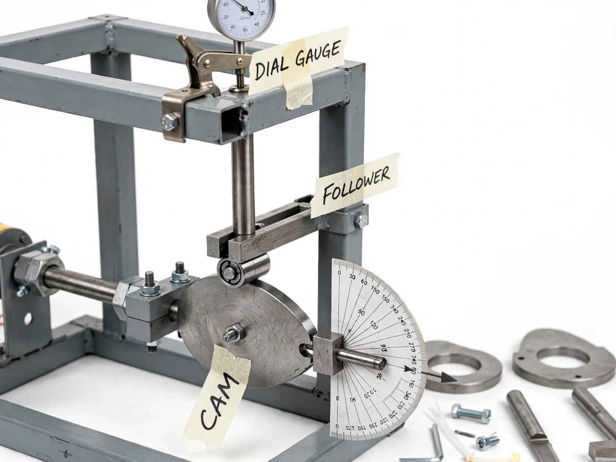
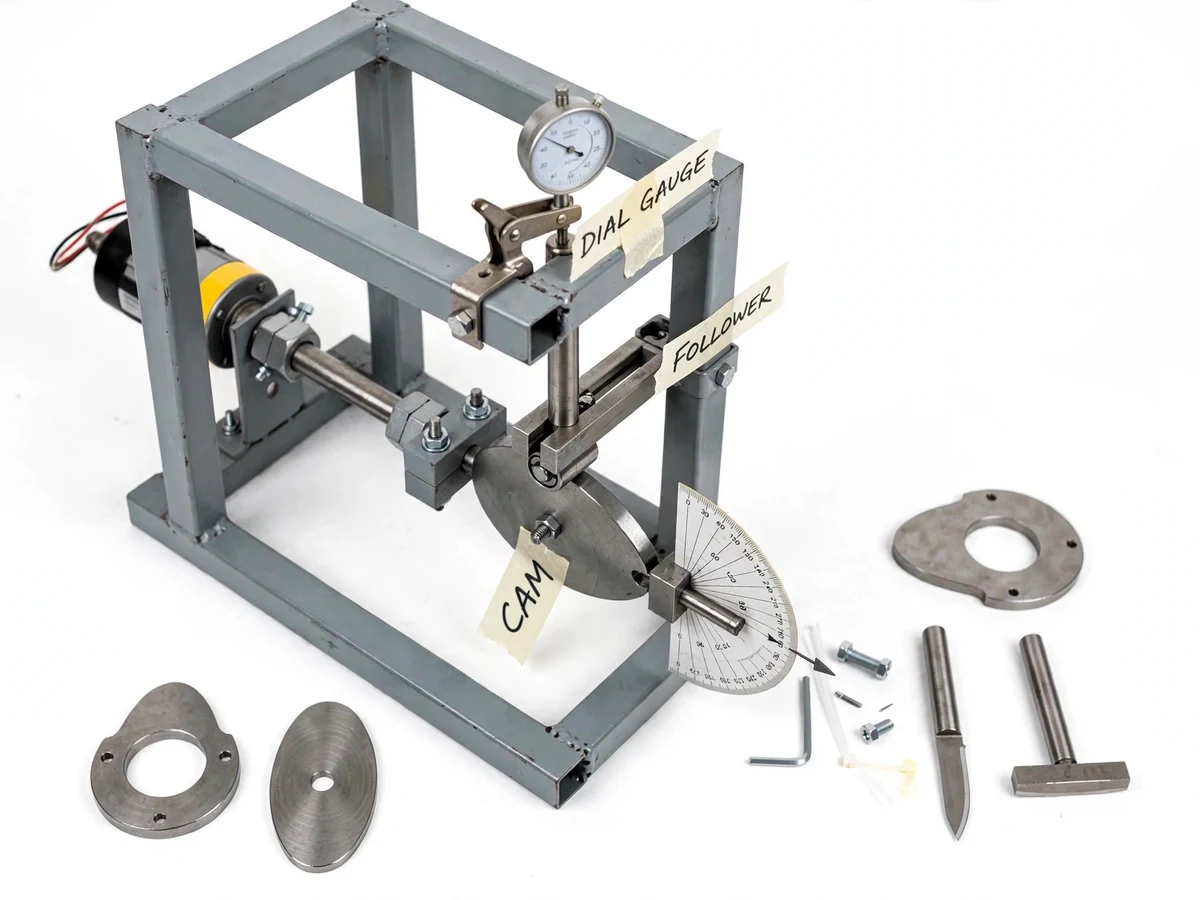
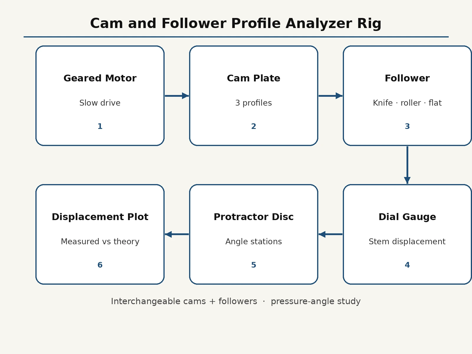
Cams convert rotary motion into precisely timed linear or oscillating motion — in engine valve trains, automatic lathes, packaging machines and textile looms. Students learn to draw displacement, velocity and acceleration diagrams for standard cam profiles, but the link between the drawn curve and the physical cam stays abstract: few ever measure what a real follower actually does on a real cam. This project closes that gap with a bench-top analyzer rig. A geared motor rotates the cam shaft slowly and uniformly; three interchangeable cam plates (simple harmonic motion, uniform velocity, cycloidal rise-dwell-return) mount on the shaft in turn; and three follower types (knife-edge, roller, flat-faced) with a dial gauge ride each cam. At marked cam angles the student records follower displacement, plots the measured displacement diagram, and compares it with the theoretical curve — seeing profile errors, follower differences and dwell behavior as measured facts.
Geared motor that rotates the cam plate at a slow, steady speed.
Follow the working sequence
How it works
- The chosen cam plate is mounted on the cam shaft and the chosen follower is fitted on its vertical stem above the cam.
- The geared motor rotates the cam slowly; the protractor disc on the shaft shows the cam angle at marked stations.
- At each angle station the student reads the follower displacement on the dial gauge and records it on the data sheet.
- After a full revolution, the measured readings are plotted as the displacement diagram on the graph sheet.
- The measured curve is overlaid against the theoretical profile supplied for that cam, and deviations are noted and explained.
- The study is repeated for the other cam plates and follower types, building the comparison set for the report.
Tech stack:
- Fabricated MS frame with cam shaft
- Three cam plates (SHM, uniform velocity, cycloidal)
- Knife-edge, roller and flat-faced followers
- Geared DC motor drive
- Protractor disc for cam-angle marking
- Dial gauge (0.01 mm least count)
- Plummer block bearings
- Data sheets and graph formats
| Parameter | Value |
|---|---|
| Cam lift | Approximately 20 mm (design target) |
| Cam plates | 3 profiles: SHM, uniform velocity, cycloidal (marked) |
| Followers | Knife-edge, roller, flat-faced (interchangeable) |
| Cam speed | Approximately 5–10 rpm (design target) |
| Dial gauge least count | 0.01 mm (instrument specification) |
| Base circle | Approximately 50 mm radius (design target) |
| Overall size | Approximately 600 × 400 × 500 mm (design target) |
Project features
- [Three interchangeable cam plates] Laser-marked cam plates for SHM, uniform-velocity and cycloidal motion, each with the theoretical displacement data supplied.
- [Three follower types] Knife-edge, roller and flat-faced followers on a common stem, so the student compares how follower geometry changes the measured motion.
- [Dial-gauge displacement measurement] A dial gauge on the follower stem reads displacement at each cam-angle station marked on the protractor disc.
- [Slow uniform drive] A geared motor with a marked protractor disc gives a slow, steady cam rotation suitable for manual reading at each angle.
- [Displacement plotting sheets] Ready graph sheets for measured vs theoretical displacement diagrams, plus velocity derivation by graphical differentiation.
- [Pressure-angle study] The manual includes a procedure to observe and note the pressure-angle effect with the flat-faced vs knife-edge follower.
- [Fabrication drawings] Dimensioned drawings of the frame, shaft, cam plates and follower assembly for the report and viva.
What is included
- Fully fabricated cam and follower rig with all cam plates and followers
- Dial gauge and protractor disc fitted on the rig
- Cam-profile theory manual with theoretical displacement data
- Measurement data sheets and displacement graph formats
- Dimensioned fabrication drawings
- Project report PDF (cam theory, rig design, measurement methodology, comparison)
- PPT presentation for final review
- Viva Q&A preparation document (cam profiles, pressure angle, jump phenomenon, follower types)
Limitations & prerequisites
- Displacement readings are taken manually at angle stations — no values are claimed as measured before the student's own experiment.
- Manual reading limits the number of angle stations; the manual recommends 15° or 30° steps with repeat runs for consistency.
- The dial gauge measures the follower used; knife-edge follower readings include the geometric sharpness effect, discussed in the report.
- Slow-speed rig only: dynamic effects like follower jump at high speed are explained in theory, not demonstrated (high-speed module is future scope).
- Cam plates are fixed profiles; a custom profile plate can be ordered as an extension, not in the base build.
Frequently Asked Questions
What does the rig actually measure?
Follower displacement at marked cam angles, read on a dial gauge. From these the student plots the measured displacement diagram and compares it with the theoretical curve for each cam profile.
Why three cam profiles?
SHM, uniform-velocity and cycloidal cams have distinctly different acceleration behavior. Measuring all three shows why cycloidal profiles are preferred where smooth acceleration matters.
Why three follower types?
Follower geometry changes the contact and the effective motion — the roller reduces wear, the flat face changes the pressure angle behavior. The rig lets the student see the difference in data, not just diagrams.
What is follower jump, and is it covered?
Jump is the follower losing contact with the cam at high speed due to inertia. The rig runs too slowly to show it physically, so it is covered in the theory manual and viva Q&A as a design consideration.
Is this project suitable for a final-year project?
Yes — for Mechanical and Mechatronics programs. It converts cam-profile theory into a real measurement-and-comparison experiment. Suitable for B.E./B.Tech final-year projects in Mechanical and Mechatronics Engineering.
Components & software requirements
- Fabricated MS frame with cam shaft
- Three cam plates (SHM, uniform velocity, cycloidal)
- Knife-edge, roller and flat-faced followers
- Geared DC motor drive
- Protractor disc for cam-angle marking
- Dial gauge (0.01 mm least count)
- Plummer block bearings
- Data sheets and graph formats
Delivery information
Built-to-order project. Delivery timeline is shared after order confirmation based on current queue.
Support terms
Complete documentation, setup guide, and viva preparation included. Support for setup and explanation provided.
Download free synopsis (PDF)
Enter your name and WhatsApp number — the synopsis PDF downloads immediately. We may send occasional project updates on WhatsApp; no spam.