
More project photos (2)
The problem
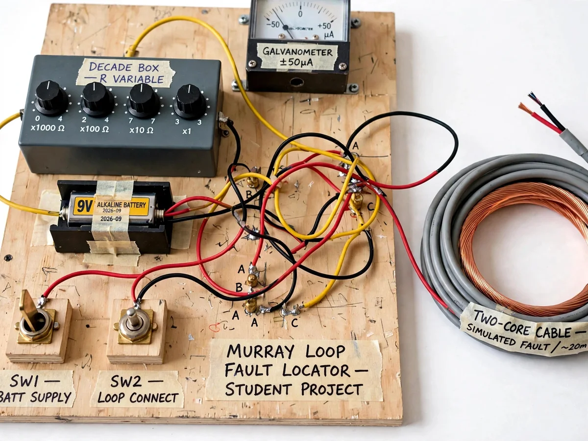
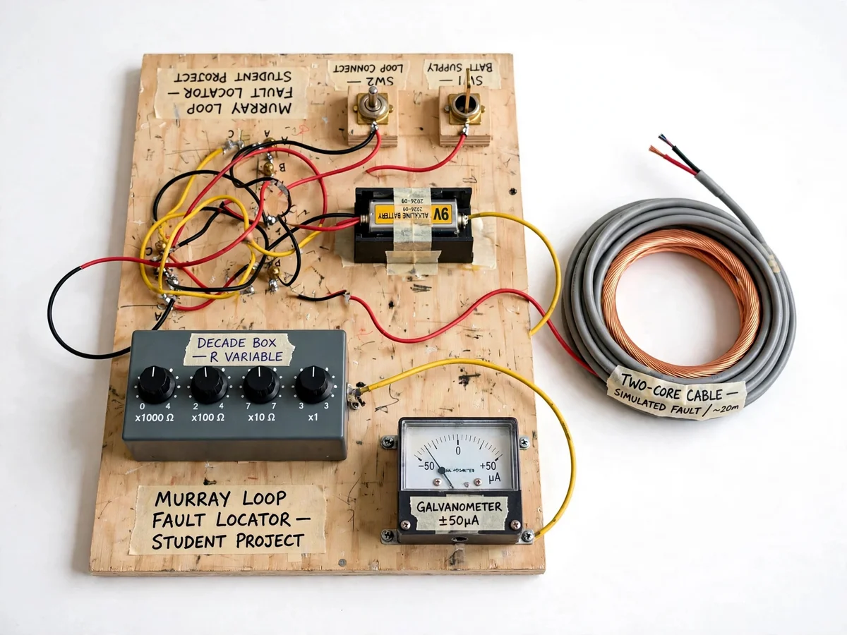
When an underground distribution cable fails, the hardest part of the repair is finding where it failed. Digging up a road is slow and expensive, while commercial fault locators are costly instruments students never open up. The Murray loop method is the classical textbook answer: a bridge technique that turns the faulted cable itself into one arm of a Wheatstone bridge. The faulty core is connected to a sound core of the same cable at the far end, forming a loop; at the test end, two ratio arms and a variable balance arm are adjusted until a galvanometer reads null. At balance, the ratio of the balance resistance to the total loop resistance gives the distance from the test end to the fault. This project turns that theory into a hands-on rig: a wooden test panel carrying a decade resistance box, a center-zero galvanometer, a DC supply, knife switches and a two-core copper demo cable with fault taps at known distances, so the student balances the bridge, computes the fault distance, and verifies it against the actual tap.
How it works
- The far end of the demo cable is prepared by joining the faulted core to a sound core, forming the Murray loop, and the near end is wired to the bridge terminals.
- The 9 V DC supply is switched on through the battery knife switch, energizing the bridge with the galvanometer protected by a series resistor.
- The operator selects the fault type mode (earth or short-circuit) and connects the appropriate bridge terminals.
- The decade resistance box is adjusted in coarse-then-fine steps while watching the galvanometer, until the needle holds at zero — the null-balance point.
- The balance resistance and the fixed ratio-arm values are recorded from the dials.
- The fault distance from the test end is computed from the standard Murray loop ratio, and checked against the known tap position on the demo cable.
- The fault tap is moved to another position and the measurement is repeated, building a small table of computed vs actual distances for the report.
Tech stack:
- Murray loop / Wheatstone bridge theory
- Center-zero analog galvanometer (typical ±50 µA)
- Decade resistance box (balance arm)
- 9 V DC bridge supply with knife switches
- Two-core copper demo cable with fault taps
- Banana sockets and hookup wiring
- Fault-distance ratio mathematics
- Electrical measurement procedure
| Parameter | Value |
|---|---|
| Bridge supply | 9 V DC battery (design) |
| Null detector | Center-zero galvanometer, typical ±50 µA (datasheet class) |
| Balance arm | Decade box, 1 Ω–10 kΩ in 1 Ω steps (typical) |
| Ratio arms | Fixed precision resistors (design) |
| Demo cable | Two-core copper, approximately 20 m (design) |
| Fault taps | 3 positions at known distances (design) |
| Fault types handled | Earth fault and core-to-core short, fault resistance below ~50 Ω (design target) |
| Location resolution | Approximately 1 m on the demo cable (design target) |
| Sound core | Required — same gauge and length as faulted core (condition of the method) |
Project features
- [Working Murray loop bridge] The faulted core is looped with a sound core at the far end so the two cores form the unknown arms of a Wheatstone bridge, exactly as the textbook method requires.
- [Galvanometer null detector] A center-zero analog galvanometer (typical ±50 µA) shows bridge imbalance; the student adjusts the balance arm until the needle rests at zero.
- [Tappable demo cable] A two-core copper cable of known length carries fault taps at known distances, simulating earth and short-circuit faults the student must locate blind and then verify.
- [Variable balance arm] A decade resistance box provides the adjustable arm in fine steps, so balance readings are repeatable and the math is traceable.
- [Fault-distance worksheet] A step-by-step procedure sheet walks through the balance, the ratio formula, and the distance calculation, with a worked example.
- [Earth and short-circuit modes] The rig demonstrates both fault types the Murray loop handles — core-to-earth and core-to-core shorts — with separate tap sets.
- [Buyer-run verification procedure] The build includes a calibration routine the student performs on their own rig: balance on each known tap and record the computed vs actual distance.
What is included
- Assembled Murray loop test panel with galvanometer, decade box, switches and terminals
- Two-core demo cable with tappable fault points at known distances
- Wiring and schematic diagram of the bridge connections
- Fault-distance calculation worksheet with worked example
- Buyer-run balance and verification procedure
- Project report PDF (background, bridge theory, methodology, readings)
- PPT presentation for final review
- Viva Q&A preparation document (bridge balance, fault types, error sources)
Limitations & prerequisites
- The Murray loop locates low-resistance earth and short-circuit faults only — open-circuit faults need the Varley loop or a different method.
- A sound core of the same gauge and length must be available for the loop-back; without it the method cannot be applied.
- Accuracy degrades as fault resistance rises; the design target holds for fault resistance below approximately 50 Ω.
- Cable resistance changes with temperature — the procedure notes a correction, but ambient drift adds error on hot days.
- The demo cable is approximately 20 m; scaling the math to kilometre-scale feeders is explained in the report but not physically demonstrated.
- This is the classical bridge method by design — no TDR or pulse-echo equipment is involved.
Frequently Asked Questions
What is the Murray loop method?
It is a Wheatstone-bridge technique for locating earth and short-circuit faults in underground cables. The faulted core is joined to a sound core at the far end to form a loop; at the test end, ratio arms and a variable arm are balanced against a galvanometer, and the balance reading gives the fault distance as a fraction of the total loop length.
How is it different from the Varley loop?
Both are bridge methods, but the Murray loop needs one sound core looped with the faulty core, while the Varley loop uses a single variable arm and a different balance arrangement. The Murray loop is the standard choice for earth and short-circuit faults; the Varley loop handles open-circuit faults.
Why is a sound core needed?
The bridge compares the resistance from the test end to the fault against the rest of the loop. The sound core provides the known return path that completes the loop — without it there is no closed bridge and no balance point.
Which faults can it locate?
Earth faults (core to sheath/earth) and core-to-core short circuits, provided the fault resistance is low. High-resistance and open-circuit faults fall outside this method's range.
How accurate is the demo?
The design target is location within about 1 m on the 20 m demo cable when the fault resistance is low. The report includes the student's own computed-vs-actual table, so the achieved figure is documented honestly from their readings.
Is this project suitable for a final-year project?
Yes — for Electrical Engineering programs. It demonstrates bridge measurement theory, fault-location practice, and careful experimental procedure in one build. Suitable for B.E./B.Tech final-year projects in Electrical Engineering.
Components & software requirements
- Murray loop / Wheatstone bridge theory
- Center-zero analog galvanometer (typical ±50 µA)
- Decade resistance box (balance arm)
- 9 V DC bridge supply with knife switches
- Two-core copper demo cable with fault taps
- Banana sockets and hookup wiring
- Fault-distance ratio mathematics
- Electrical measurement procedure
Delivery information
Built-to-order project. Delivery timeline is shared after order confirmation based on current queue.
Support terms
Complete documentation, setup guide, and viva preparation included. Support for setup and explanation provided.