
More project photos (3)
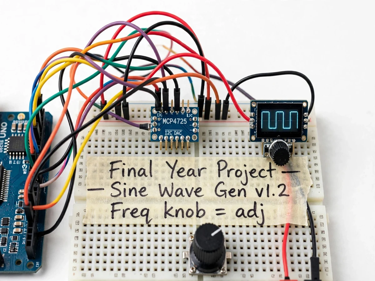
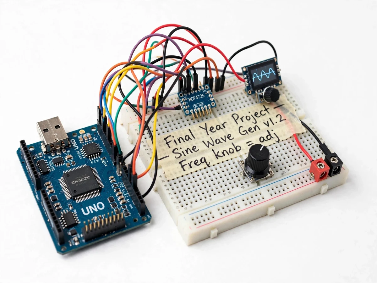
The problem
A benchtop function generator is one of the most-used instruments in any electronics lab, and its price is exactly what keeps it out of many student setups. Rather than buying one, this project builds the instrument's core function with parts totaling well under a typical student's budget: an Arduino Uno synthesizes the waveform mathematically, an MCP4725 12-bit DAC converts it to a true analog voltage over I2C, a rotary knob and buttons set frequency and amplitude, and a 128×64 OLED displays the waveform type, frequency and amplitude. A lookup-table engine with 256 samples per cycle and a timer-driven update loop holds the frequency steady; at higher frequencies the achievable fidelity is set by the update budget, which the report derives explicitly — the project is honest about this ceiling. Beyond the instrument itself, the build teaches the real embedded skills: timer interrupts, I2C peripheral interfacing, sample buffering and DAC resolution budgeting. A calibration procedure trims output offset and level, and the design is deliberately documented as a lab aid, not a replacement for calibrated test equipment.
Turns the knob and presses buttons to control the generator.
How it works
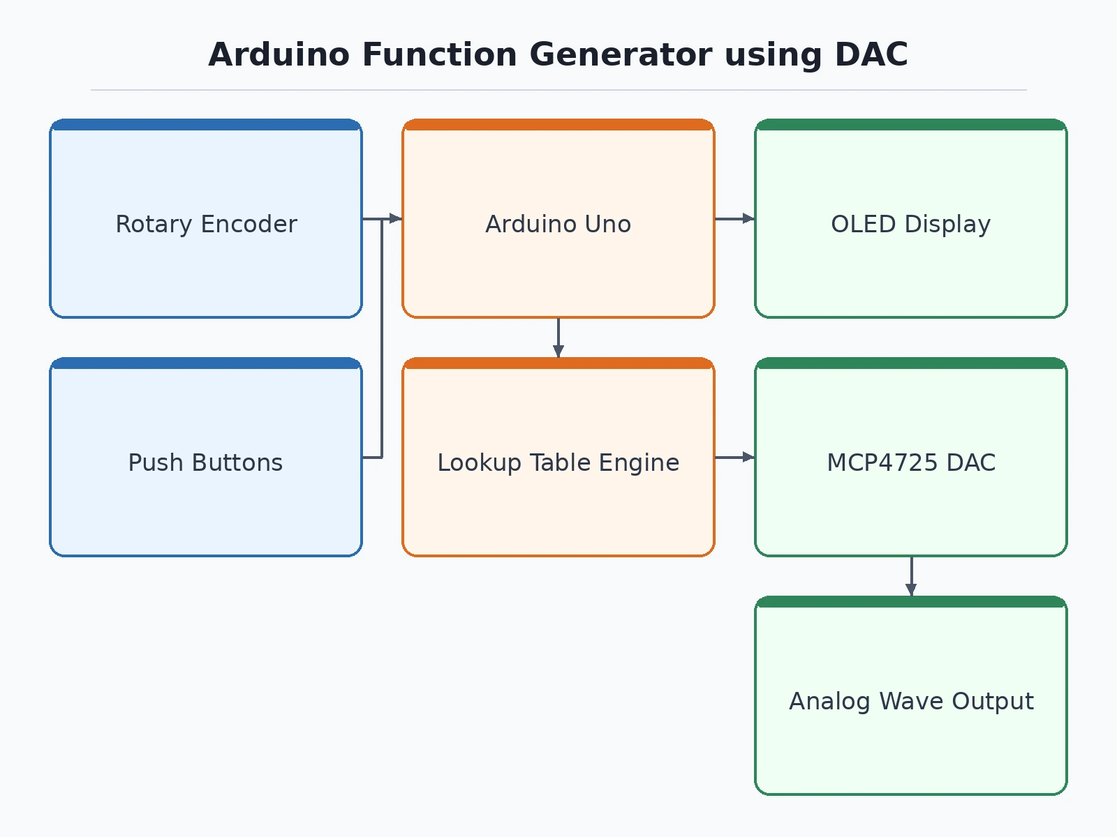
- A 256-sample sine lookup table is generated in firmware at startup; triangle and sawtooth tables are derived from it.
- A hardware-timer interrupt fires at the sample rate dictated by the target frequency; each tick advances the table phase accumulator and writes the sample to the MCP4725 over I2C.
- The rotary encoder adjusts the frequency setpoint from 0.1 Hz to 1 kHz; push buttons cycle the waveform and set amplitude steps.
- The SSD1306 OLED redraws on every UI change, showing waveform type, frequency, amplitude and a live mini preview of the table being output.
- At 1 kHz the 256-sample table needs a 256 kHz sample rate, so the firmware switches to coarser resolution at the top end — the fidelity tradeoff is measured and documented.
- The calibration procedure trims the output offset and level against a multimeter; the report records the trimming steps and typical residual error.
Tech stack:
- Arduino Uno (ATmega328P, timer-interrupt sample engine)
- MCP4725 12-bit I2C DAC (true analog output)
- SSD1306 128×64 OLED over I2C (UI readout)
- Rotary encoder + push buttons (frequency/waveform/amplitude control)
- Arduino IDE, C/C++ firmware
- Optional op-amp buffer stage for driving heavier loads
| Parameter | Value |
|---|---|
| Waveforms | Sine, square, triangle, sawtooth |
| Frequency range | 0.1 Hz to 1 kHz (set via rotary encoder) |
| DAC | MCP4725, 12-bit, I2C |
| Sample engine | 256-sample lookup table, timer-interrupt driven |
| Display | SSD1306 128×64 OLED (type, frequency, amplitude, live preview) |
| Controls | Rotary encoder (frequency), push buttons (waveform, amplitude steps) |
| Output | Analog via DAC; optional op-amp buffer for load driving |
| Power | 5 V (USB or barrel jack) |
| Calibration | Multimeter-based offset and level trim; documented procedure |
| Accuracy | Typical residual error after calibration depends on trim care; procedures provided, no pre-claimed lab-grade precision |
Project features
- [Four waveforms] Sine, square, triangle and sawtooth generated from 256-sample lookup tables (square from the sine table at 50% duty).
- [Wide range, real spec] 0.1 Hz to 1 kHz output; fidelity limits at the top end are derived from the DAC update budget and stated honestly in the report.
- [True analog output] MCP4725 12-bit DAC over I2C — a smooth analog signal, not a PWM-filtered approximation.
- [Knob-and-button UI] Rotary encoder sets frequency, push buttons select waveform and amplitude steps; no phone or PC required to operate it.
- [OLED readout] 128×64 SSD1306 display shows waveform type, frequency, amplitude and a live mini waveform preview.
- [Timer-driven engine] A hardware-timer update loop keeps the sample rate steady independent of the UI loop, so the knob never glitches the output.
- [Calibration procedure] Step-by-step trimming of output offset and level with a multimeter, documented in the report and calibration guide.
- [Breadboard-friendly build] Assembled on a breadboard or stripboard from standard modules — no custom PCB required.
What is included
- Complete Arduino firmware (lookup-table engine, timer ISR, I2C drivers, UI)
- Wiring diagram and connection map (breadboard layout)
- Component list with exact part numbers
- Calibration guide (offset/level trim procedure)
- Project report PDF (DAC interfacing, sample budgeting, calibration, limitations)
- PPT presentation for final review
- Viva Q&A preparation document (timer interrupts, I2C, DAC resolution, Nyquist)
- Assembly and operation guide
Advantages
- An Arduino Uno driving an MCP4725 12-bit I2C DAC produces a true analog output - sine, square, triangle and sawtooth from 256-sample lookup tables - not a PWM-filtered approximation.
- The 0.1 Hz to 1 kHz range covers audio-range and lab exercises, with the square wave taken from the sine table at 50% duty.
- A rotary encoder sets frequency, push buttons select waveform and amplitude steps, and no phone or PC is required to operate it.
- The 128x64 SSD1306 OLED display shows waveform type, frequency, amplitude and a live mini waveform preview.
- A hardware-timer update loop keeps the sample rate steady independent of the UI loop, so the knob never glitches the output.
- A step-by-step calibration procedure trims output offset and level with a multimeter, and the build is breadboard-friendly from standard modules with no custom PCB required.
Disadvantages
- 0.1 Hz to 1 kHz covers audio-range and lab exercises, but this is not a replacement for a lab-grade signal generator: no calibrated precision, no modulation modes, no arbitrary-waveform upload.
- High-frequency fidelity is bounded by the DAC update budget; the report derives the limit and shows measured waveform quality rather than claiming more than the hardware delivers.
- Output impedance is the DAC's own unless the optional op-amp buffer is added - it cannot drive low-impedance loads or deliver real power.
- The build is an educational lab aid, not certified test equipment; accuracy is limited by the 12-bit DAC and by the builder's calibration care.
- Breadboard assembly is fine for the demo, but noisy environments or long leads will degrade the output; a boxed build is the documented recommendation.
Limitations & prerequisites
- 0.1 Hz–1 kHz covers audio-range and lab exercises, but this is not a replacement for a lab-grade signal generator: no calibrated precision, no modulation modes, no arbitrary-waveform upload.
- High-frequency fidelity is bounded by the DAC update budget; the report derives the limit and shows measured waveform quality rather than claiming more than the hardware delivers.
- Output impedance is the DAC's own unless the optional op-amp buffer is added — it cannot drive low-impedance loads or deliver real power.
- The build is an educational lab aid, not certified test equipment; accuracy is limited by the 12-bit DAC and by the builder's calibration care.
- Breadboard assembly is fine for the demo but noisy environments or long leads will degrade the output; a boxed build is the documented recommendation.
Frequently Asked Questions
Which DAC is used and why?
The MCP4725 — a 12-bit I2C DAC — because it produces a true analog output and interfaces to the Uno over just two I2C lines, unlike PWM-through-a-filter hacks.
What frequency range does it cover?
0.1 Hz to 1 kHz, set from the rotary encoder. The report explains honestly how the sample budget limits fidelity at the top of the range.
How accurate is the output?
It is a student lab aid, not calibrated equipment. A multimeter-based calibration procedure trims offset and level, and the residual error depends on the builder's trim care — the project does not pre-claim lab-grade precision.
Is an op-amp buffer included?
The base build drives the DAC output directly; the optional op-amp buffer stage for heavier loads is documented as an add-on with its own wiring diagram.
What will I receive with the project?
Arduino firmware, wiring diagram, component list, calibration guide, project report, PPT, viva Q&A document and assembly guide. Suitable for B.E./B.Tech final-year projects in Electronics, Electrical and related branches.
Components & software requirements
- Arduino Uno (ATmega328P, timer-interrupt sample engine)
- MCP4725 12-bit I2C DAC (true analog output)
- SSD1306 128×64 OLED over I2C (UI readout)
- Rotary encoder + push buttons (frequency/waveform/amplitude control)
- Arduino IDE, C/C++ firmware
- Optional op-amp buffer stage for driving heavier loads
Delivery information
Built-to-order project. Delivery timeline is shared after order confirmation based on current queue.
Support terms
Complete documentation, setup guide, and viva preparation included. Support for setup and explanation provided.
Download free synopsis (PDF)
Enter your name and WhatsApp number — the synopsis PDF downloads immediately. We may send occasional project updates on WhatsApp; no spam.