
More project photos (3)
The problem
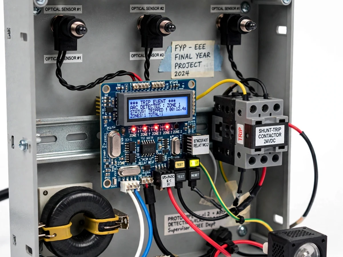
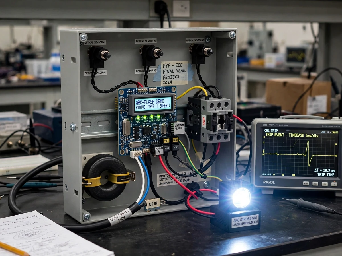
An arc flash — the explosive release of energy when an arc fault strikes inside switchgear — can reach thousands of degrees in milliseconds, and conventional overcurrent relays with their inverse-time curves simply cannot clear it fast enough to limit the damage. Dedicated arc-flash protection relays solve this with a different signature: they watch for the blinding light of the arc with optical sensors and confirm with overcurrent, tripping in a few milliseconds because light arrives long before current-time curves would act. This project builds that protection concept as a safe student demonstrator: a model switchgear panel fitted with zoned optical arc sensors and a current transformer, a high-speed controller implementing light-plus-current trip logic, and a demo shunt-trip breaker as the trip target. A high-intensity LED arc simulator provides the "arc" for testing — no real arcing is ever created — so the speed and selectivity of optical detection can be demonstrated and measured safely on the bench.
Point photodiode modules watching the panel zones.
Follow the working sequence
How it works
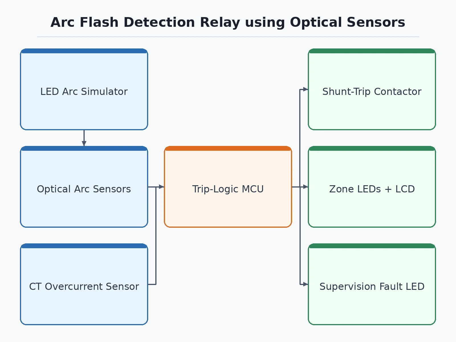
- The optical sensors watch their panel zones continuously; their signals feed fast comparators with an adjustable light threshold.
- A current transformer on the demo feeder measures load current; its signal feeds an adjustable overcurrent threshold stage.
- Under normal conditions neither threshold is crossed; the controller holds the trip output and runs sensor supervision in the background.
- The LED arc simulator fires a high-intensity pulse into a zone while the test load draws overcurrent — the arc-plus-fault signature.
- With light AND current thresholds crossed together, the controller issues the trip within its design-target time, driving the shunt-trip contactor open.
- The zone LED latches to show which sensor saw the arc, and the event is time-stamped into the log.
- Light without current (simulated flash) or current without light (plain overload) produces no trip — demonstrating the supervision logic; a manual reset restores the demo breaker.
Tech stack:
- High-speed microcontroller (trip logic, supervision, event logging)
- Point optical arc-light sensor modules (photodiode-based, fiber-coupled option)
- Fast comparator stage for the light threshold
- Current transformer with burden resistor and overcurrent threshold stage
- Shunt-trip contactor as the demo breaker
- High-intensity LED strobe arc-light simulator
- Zone LEDs and LCD for event display
- Firmware in C/C++; oscilloscope timing-measurement procedure
| Parameter | Value |
|---|---|
| Detection principle | Optical arc light + overcurrent supervision |
| Trip time | Design target <10 ms light-to-trip-contact (component-derived) |
| Sensor zones | 2–3 point optical sensors with zone indication |
| Current supervision | CT-based, adjustable overcurrent threshold |
| Trip output | Shunt-trip contactor drive (demo breaker) |
| Arc simulation | LED strobe arc-light simulator (safe, no real arcing) |
| Supervision | Continuous sensor health/fault monitoring |
| Event recording | Time-stamped trip log on LCD |
Project features
- [Optical arc sensors] Point light sensors (photodiode modules, fiber-coupled option) watch the zones of the demo panel, shielded and filtered against ambient light.
- [Light-plus-current trip logic] A trip issues only when intense arc light AND overcurrent coincide — the industrial supervision principle that stops camera flashes or switching transients from causing nuisance trips.
- [High-speed trip output] Design-target sub-10 ms from light detection to trip contact (derived from sensor, comparator and controller delays), driving a demo shunt-trip contactor.
- [Zone-selective sensing] Two to three sensor zones with individual zone LEDs identify which panel zone saw the arc — the basis of selective tripping discussions.
- [Safe arc simulator] A high-intensity LED strobe module simulates arc light for testing and timing measurement; no real arc flash is ever produced.
- [Sensor supervision] Continuous health checking flags a disconnected, blinded or failed sensor with a fault LED — supervision is part of real relay design.
- [Event log] Time-stamped trip and supervision events on the display give the report its test record.
What is included
- Demo switchgear panel with zoned optical sensors and CT
- Relay controller board with firmware (trip logic, supervision, logging)
- Shunt-trip contactor as the demo breaker
- LED arc-light simulator module
- Circuit schematic and wiring diagram
- Bill of materials with part numbers and sourcing notes
- Project report PDF (arc-flash background, light+current principle, buyer-run timing procedure)
- PPT presentation for final review
- Viva Q&A preparation document (arc flash, protection speed, optical detection, relay supervision)
- Setup and demo guide (simulator tests, timing measurement, safe operation)
Advantages
- Point optical sensors watch zones of the demo panel, shielded and filtered against ambient light, with a fiber-coupled option.
- A trip issues only when intense arc light and overcurrent coincide, the industrial supervision principle that stops camera flashes or switching transients causing nuisance trips.
- Zone-selective sensing across two to three sensor zones with individual zone LEDs identifies which panel zone saw the arc.
- A high-intensity LED strobe module simulates arc light safely for testing and timing measurement, with no real arc flash ever produced.
- Continuous sensor supervision flags a disconnected, blinded or failed sensor with a fault LED, and time-stamped trip and supervision events give the report its test record.
Disadvantages
- This is an academic demonstrator, not a certified protection relay, with no type testing or arc-flash containment certification, and it must never be presented as protection for real switchgear.
- It cannot be tested against a real arc flash in a student lab, so all timing and logic tests use the LED arc simulator.
- The sub-10 ms trip figure is a design target derived from sensor, comparator and controller propagation delays, not a calibrated measurement.
- The demo panel runs at safe low voltage, so sensor behaviour at real switchgear light levels and distances is discussed from literature, not demonstrated.
- Nuisance-immunity is demonstrated with simulated stimuli only, and qualified supervision is required for all powered testing of the panel and contactor.
Limitations & prerequisites
- Academic demonstrator, not a certified protection relay: it has no type testing, no arc-flash containment certification (e.g. IEEE C37.20.7 / IEC 62271 arc testing), and must never be presented as protection for real switchgear.
- It cannot be tested against a real arc flash in a student lab — all timing and logic tests use the LED arc simulator, and the report states this openly.
- The sub-10 ms trip figure is a design target derived from sensor, comparator and controller propagation delays, not a calibrated measurement; the report includes a buyer-run oscilloscope procedure to measure the actual time.
- The demo panel runs at safe low voltage; sensor behavior at real switchgear light levels and distances is discussed from literature, not demonstrated.
- Nuisance-immunity (light without current, current without light) is demonstrated with simulated stimuli only.
- Qualified supervision is required for all powered testing of the panel and contactor.
Frequently Asked Questions
Is this project suitable for a final-year project?
Yes — for Electrical Engineering programs. It demonstrates protection philosophy, high-speed sensing, light-plus-current supervision logic and relay testing practice, with measurable trip timing for the report.
Do you create a real arc flash for testing?
Never. A high-intensity LED strobe simulates arc light safely; real arc flashes are destructive events tested only in certified high-power laboratories.
Why light plus current, not light alone?
Light alone would nuisance-trip on camera flashes or switching transients; current supervision confirms a genuine fault. The demo proves both halves: each stimulus alone produces no trip.
Is the trip time measured or claimed?
Sub-10 ms is a design target derived from component delays. The report includes a buyer-run oscilloscope procedure so you measure and document the actual light-to-trip time on your build.
Can this protect real switchgear?
No. It is an educational demonstrator with no type testing or arc-containment certification; real installations use certified relays installed by qualified engineers.
What will I receive with the project?
The demo panel with sensors and CT, relay controller with firmware, shunt-trip contactor, LED arc simulator, schematics, BOM, project report PDF, PPT, viva Q&A and a setup/demo guide. Suitable for B.E./B.Tech final-year projects in Electrical Engineering.
Components & software requirements
- High-speed microcontroller (trip logic, supervision, event logging)
- Point optical arc-light sensor modules (photodiode-based, fiber-coupled option)
- Fast comparator stage for the light threshold
- Current transformer with burden resistor and overcurrent threshold stage
- Shunt-trip contactor as the demo breaker
- High-intensity LED strobe arc-light simulator
- Zone LEDs and LCD for event display
- Firmware in C/C++; oscilloscope timing-measurement procedure
Delivery information
Built-to-order project. Delivery timeline is shared after order confirmation based on current queue.
Support terms
Complete documentation, setup guide, and viva preparation included. Support for setup and explanation provided.
Download free synopsis (PDF)
Enter your name and WhatsApp number — the synopsis PDF downloads immediately. We may send occasional project updates on WhatsApp; no spam.
Development of an Active Optical Lens for Arc Flashing Detection (Sensors, 2023)