
More project photos (2)
The problem
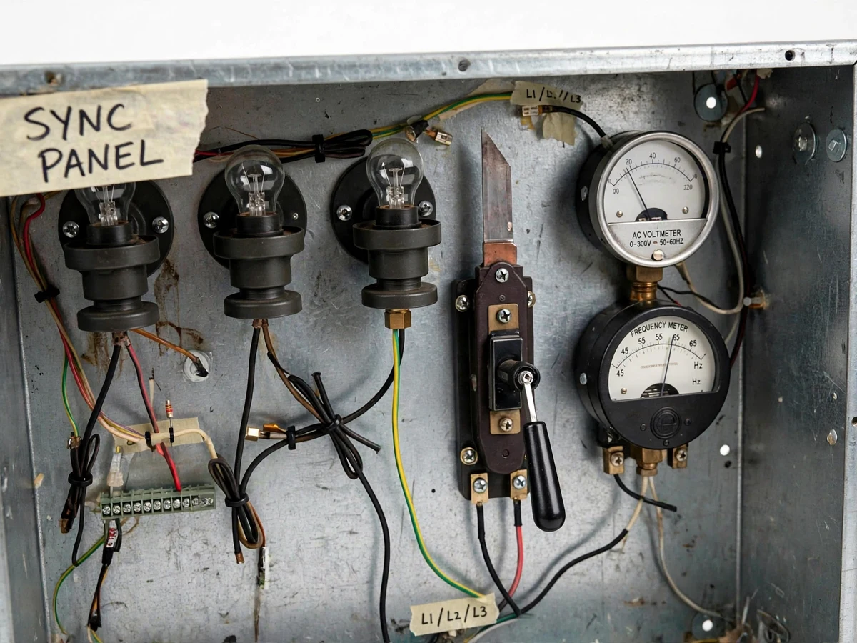
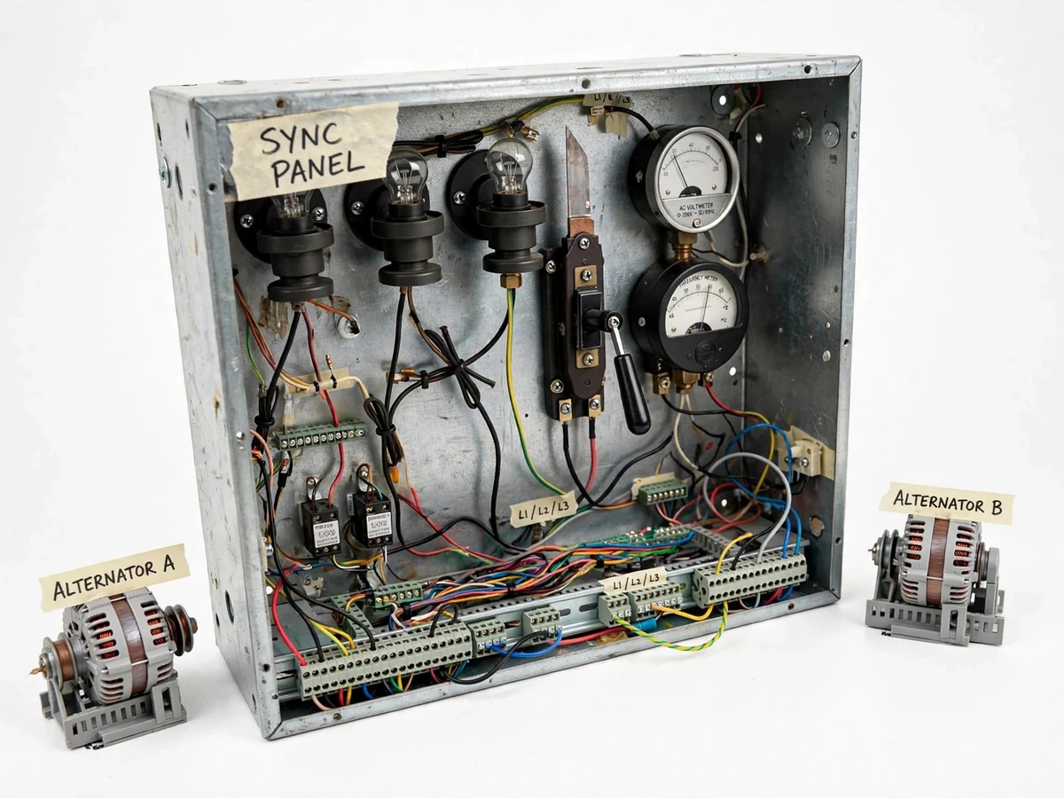
Paralleling an alternator with a live bus is one of the most safety-critical operations in power systems, and the conditions — equal voltage, equal frequency, same phase sequence, phase coincidence — are taught as a list students memorize without ever witnessing. This project makes them visible. A steel synchronization panel carries three dark-lamp indicators wired across the synchronizing switch, an AC voltmeter and a frequency meter, and a heavy-duty synchronizing switch. Two miniature alternator models feed the panel; as the incoming machine's speed is adjusted, the lamps beat in and out, slow down, and finally go dark together — the exact moment the switch may be closed. The demonstration turns a memorized list into an observed event.
How it works
- One alternator model is energized as the "bus"; its voltage and frequency are read on the panel meters.
- The second alternator (incoming) is started and its excitation adjusted until its voltage matches the bus voltage on the AC voltmeter.
- The incoming machine's speed is adjusted until its frequency, read on the frequency meter, matches the bus frequency.
- With both machines near match, the three lamps beat bright and dark in sequence; the student adjusts speed to slow the beat toward zero.
- At the instant all three lamps are dark together — phase coincidence — the synchronizing switch is closed, paralleling the machines.
- The procedure documents the warning signs of wrong phase sequence (rotating lamp brightness) and what to do about it.
Tech stack:
- Steel synchronization panel enclosure
- Three dark-lamp indicators with holders
- Analog AC voltmeter (0-300 V class)
- Analog frequency meter (45-65 Hz class)
- Synchronizing knife switch
- Two miniature alternator models
- DIN terminal blocks (L1/L2/L3 labeled)
- Demonstration procedure manual
| Parameter | Value |
|---|---|
| Method | Dark-lamp synchronization (classic method) |
| Voltage matching | Analog AC voltmeter, approximately 0-300 V class (design target) |
| Frequency matching | Analog frequency meter, approximately 45-65 Hz class (design target) |
| Paralleling device | Synchronizing knife switch |
| Indicators | 3 x lamp holders with lamps |
| Alternators | 2 x miniature models (demonstration scale) |
| Wiring | Terminal-block based, L1/L2/L3 labeled |
| Synchronization criterion | Simultaneous lamp darkness (observed by student, not a measured figure) |
Project features
- [Dark-lamp synchronization indicators] Three lamp holders wired across the synchronizing switch show the beat between incoming and bus voltages; simultaneous darkness is the visual paralleling criterion.
- [AC voltmeter and frequency meter] Analog meters let the student match voltage and frequency of the incoming machine to the bus before attempting synchronization.
- [Synchronizing switch] A heavy-duty knife-type switch is the paralleling device, closed only at the dark-lamp instant per the procedure.
- [Two alternator models] Two miniature alternator models feed the panel, representing the bus machine and the incoming machine.
- [Terminal-block wiring] DIN-style terminal blocks with L1/L2/L3 labeling make every connection traceable for the viva.
- [Buyer-run demonstration procedure] A documented step-by-step procedure: voltage matching, frequency matching, lamp-beat observation, switch closing, and the wrong-sequence warning signs.
- [Complete viva kit] Report covering synchronous machines, paralleling conditions and the lamp methods, plus PPT and viva Q&A.
What is included
- Fabricated steel synchronization panel
- Three lamp indicators with holders and lamps
- AC voltmeter and frequency meter
- Synchronizing switch
- Two miniature alternator models
- Terminal blocks and complete labeled wiring
- Demonstration procedure manual
- Project report PDF (synchronous machines, paralleling theory, lamp methods)
- PPT presentation for final review
- Viva Q&A preparation document
Limitations & prerequisites
- The alternators are miniature demonstration models; machine parameters of real alternators are not replicated and no kW-scale claims are made.
- Synchronization timing is observed visually by the student; no synchroscope accuracy or closing-time figure is claimed.
- The panel demonstrates the method at safe low voltages; it is not connected to any real bus and must never be presented as switchgear.
- Wrong-sequence consequences are described in theory only; the demo does not and must not attempt to parallel on wrong sequence.
- Lamp brightness interpretation is qualitative; the procedure treats it as an indicator, not a measurement.
Frequently Asked Questions
What are the conditions for synchronization?
Equal voltage, equal frequency, same phase sequence, and phase coincidence (zero voltage across the synchronizing switch). The panel lets the student verify each one with instruments and lamps.
Why do the lamps go bright and dark?
The lamps see the difference between the bus and incoming voltages; as the frequency difference shrinks, the difference voltage beats slowly, and at phase coincidence it is zero — all lamps dark together.
What happens if the phase sequence is wrong?
The lamps brighten in rotation instead of together, and the procedure says explicitly: never close the switch — correct the sequence first. This is a key viva point.
Is this the method used in real power stations?
The dark-lamp method is the historical/classroom method; real stations use synchroscopes and auto-synchronizers. The report covers both and positions the panel as the teaching demonstration.
Can the panel be connected to a real supply?
No — it is a low-voltage demonstration panel fed by miniature models, and the documentation states this safety boundary clearly.
Is this project suitable for a final-year project?
Yes — for Electrical engineering programs. Synchronization is core power-systems material, and the live lamp-beat demonstration is one of the most memorable viva demos in the subject. Suitable for B.E./B.Tech final-year projects in Electrical engineering.
Components & software requirements
- Steel synchronization panel enclosure
- Three dark-lamp indicators with holders
- Analog AC voltmeter (0-300 V class)
- Analog frequency meter (45-65 Hz class)
- Synchronizing knife switch
- Two miniature alternator models
- DIN terminal blocks (L1/L2/L3 labeled)
- Demonstration procedure manual
Delivery information
Built-to-order project. Delivery timeline is shared after order confirmation based on current queue.
Support terms
Complete documentation, setup guide, and viva preparation included. Support for setup and explanation provided.