
More project photos (2)
The problem
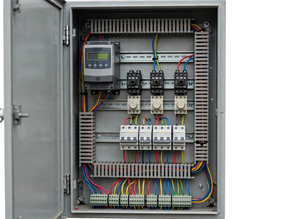
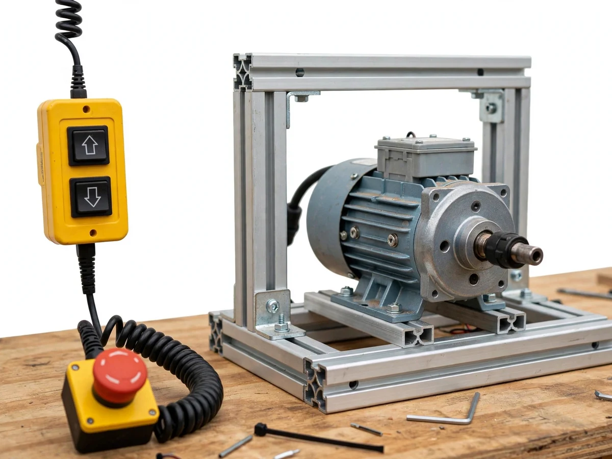
Overhead travelling cranes move heavy loads in factories and workshops, and their control gear is a classic electrical panel build: a pendant station in the operator's hand, contactors switching the travel motors, and a variable frequency drive taming the hoist motor. Direct-on-line starting jerks the load and stresses the rope and structure; the VFD instead ramps voltage and frequency, giving smooth acceleration, controlled deceleration and adjustable speed for precise load positioning. This project builds that panel for real: an enclosure with MCBs, contactors, overload relays, a control transformer, the VFD, and a wired pendant with up/down and travel pushbuttons plus a latching emergency stop. Limit-switch inputs demonstrate end-of-travel protection. Everything is wired to industrial panel practice — ferruled conductors, wire ducts, terminal numbering — so the panel itself becomes viva material.
How it works
- The operator presses a pendant pushbutton (for example, hoist up); the low-voltage control circuit energizes the corresponding direction contactor coil.
- The contactor's power poles connect the motor to the supply — for travel motors directly, for the hoist motor through the VFD output.
- The VFD ramps its output frequency from zero to the set speed over the configured acceleration time, so the hoist starts without a jerk.
- Releasing the pushbutton drops the contactor; the VFD follows its deceleration ramp to a controlled stop instead of coasting abruptly.
- Pressing the emergency stop opens the control-supply contactor, dropping every motion at once; the panel must be deliberately reset before motion resumes.
- If a travel motor reaches its end limit, the limit switch opens the direction contactor coil circuit and motion in that direction is inhibited until the opposite command is given.
Tech stack:
- Variable frequency drive (single/three-phase input, three-phase output) for the hoist motor
- Pendant pushbutton station with latching emergency stop
- 3-pole power contactors with auxiliary contacts and electrical interlocking
- Thermal overload relays and MCBs sized from motor nameplate data
- Control transformer for the low-voltage control circuit
- Limit switches for end-of-travel protection
- Small 3-phase induction motor on a test frame as the scaled demo load
- Steel enclosure with DIN rail, wire ducts and numbered terminals
| Parameter | Value |
|---|---|
| Control method | Pendant pushbutton station with latching E-stop |
| Motions controlled | Hoist (VFD), cross-travel and long-travel (contactor); demo rig shows one axis at a time |
| VFD | Single/three-phase input, three-phase output; frequency range per the supplied drive's datasheet |
| Demo motor | Small 3-phase induction motor, approximately 0.5-1 HP (nameplate of the supplied unit) |
| Starting | VFD ramp for hoist with configurable acceleration time; DOL via contactors for travel motors |
| Protection | Thermal overload relays per motor circuit; MCBs on incoming and control supplies |
| Control voltage | Stepped down via control transformer (rating of the supplied transformer) |
| Limit protection | End-of-travel limit-switch inputs for each travel direction (demonstration) |
| Panel build | Steel enclosure, DIN-rail gear, ferruled and numbered conductors, door-fixed wiring diagram |
| Demo scope | Bench-scale demonstration; not a full-size crane installation |
Project features
- Pendant pushbutton station: A handheld pendant with hoist up/down, cross-travel and long-travel pushbuttons plus a latching mushroom-head emergency stop; every command is wired back to the panel's control circuit.
- VFD soft start and speed control: A variable frequency drive on the hoist motor ramps frequency up and down for jerk-free starts and stops, with preset speeds selectable from the panel for precise load positioning.
- Contactor-based direction control: Electrically interlocked forward/reverse power contactors switch each travel motor; mechanical plus electrical interlocking prevents both directions energizing together.
- Overload and short-circuit protection: Thermal overload relays on each motor circuit and MCBs on incoming and control supplies, sized from motor nameplate data.
- Emergency stop and limit switches: The pendant E-stop drops the control supply through a contactor, and limit-switch inputs at both ends of travel demonstrate end-of-travel cut-off.
- Control transformer and indication: A control transformer steps the supply down for the control circuit, with red/green indicator lamps for supply healthy, motor running and fault trip.
- Industrial panel wiring practice: Ferruled and numbered conductors, slotted wire ducts, DIN-rail mounting and a laminated wiring diagram fixed inside the door.
- Scaled demo rig: A small 3-phase induction motor mounted on a test frame stands in for the crane motions, so pendant operation and VFD ramping can be demonstrated on a bench.
What is included
- Assembled crane control panel (enclosure with VFD, contactors, MCBs, overload relays, control transformer, indicators)
- Wired pendant pushbutton station with emergency stop
- Scaled demo rig with small 3-phase induction motor on test frame
- Complete wiring diagram, panel layout drawing and terminal chart
- Component list with ratings and nameplate data
- Project report PDF (background, VFD theory, panel design, wiring, test procedure)
- PPT presentation for final review
- Viva Q&A preparation document (VFD operation, contactor interlocking, protection sizing, pendant safety)
- Commissioning and safe-operation guide
Limitations & prerequisites
- The supplied rig is a bench-scale demonstration with a small motor: it demonstrates the control scheme faithfully, but it is not a full-size crane and is not rated for lifting real loads.
- VFD parameters (acceleration time, preset speeds, current limits) must be set from the supplied drive's manual and the demo motor's nameplate; default parameters do not suit every motor.
- Three-phase supply is needed for a full three-phase demonstration; single-phase-input VFD variants limit the demo to the drive's single-phase input rating.
- The panel is an academic prototype built for demonstration, not a certified industrial crane panel: it has not undergone type testing, and real crane installations need statutory inspection and certified components.
- Pendant cable length and enclosure rating suit indoor lab demonstration; outdoor or harsh-environment use would need higher IP ratings and proper earthing practice.
- Speed-control smoothness demonstrated is limited by the small demo motor's characteristics, not by a production hoist duty cycle.
Frequently Asked Questions
Which drive is used?
A commercial variable frequency drive (single or three-phase input, three-phase output) from an established drive family, sized for the small demo motor. The report documents the exact model supplied and its key parameters.
Does the VFD really give soft start?
Yes. The drive ramps output frequency and voltage over a configurable acceleration time, so the demo motor starts and stops smoothly; the ramp is visible on the drive's own display during the viva demo.
What power supply is needed?
A three-phase supply for the full demonstration (or single-phase within the drive's input rating). The control circuit runs at a lower voltage via the control transformer.
Is this safe to demonstrate?
The demo rig uses a small bench motor, the E-stop drops all motion, and the commissioning guide covers terminal-access and lockout rules. It remains an academic prototype, not certified lifting equipment.
Can the panel be extended to a real crane?
The control scheme (pendant, interlocked contactors, VFD, limits, E-stop) is exactly what real crane panels use, and the report explains the scaling. A real installation needs certified components and statutory inspection, which is outside this project's scope.
What will I receive?
The wired control panel, pendant station, demo motor rig, wiring diagrams, component list, report PDF, PPT, viva Q&A and the commissioning guide. Suitable for B.E./B.Tech final-year projects in Electrical and EEE.
Components & software requirements
- Variable frequency drive (single/three-phase input, three-phase output) for the hoist motor
- Pendant pushbutton station with latching emergency stop
- 3-pole power contactors with auxiliary contacts and electrical interlocking
- Thermal overload relays and MCBs sized from motor nameplate data
- Control transformer for the low-voltage control circuit
- Limit switches for end-of-travel protection
- Small 3-phase induction motor on a test frame as the scaled demo load
- Steel enclosure with DIN rail, wire ducts and numbered terminals
Delivery information
Built-to-order project. Delivery timeline is shared after order confirmation based on current queue.
Support terms
Complete documentation, setup guide, and viva preparation included. Support for setup and explanation provided.