
More project photos (2)
The problem
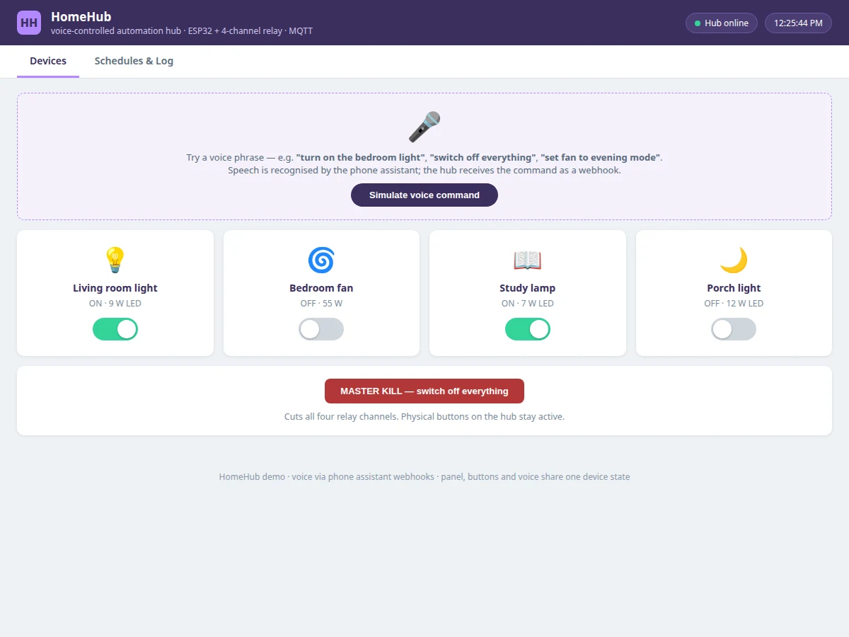
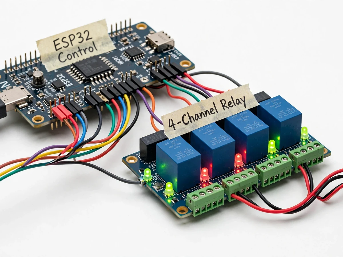
Voice control is the interface most people actually use for smart homes, yet student builds often stop at a Bluetooth app with buttons. This hub goes the honest extra step: an ESP32 with a 4-channel relay board switches four real AC loads (lamps, a fan, a demo appliance), and commands come from two interfaces — voice phrases routed through the phone's assistant via cloud webhooks, and a web control panel with the same commands as buttons. The firmware keeps one source of truth for device state, so a voice command and a panel tap never desynchronize. Schedules turn loads on/off by time, a master kill-switch cuts everything, and a current-sense option flags when a load draws beyond its configured limit. The listing is upfront about the architecture: speech recognition itself runs on the phone/cloud assistant — the ESP32 handles the automation logic, which is the engineering content of the project.
How it works
- The user speaks a command to the phone assistant; a cloud routine converts the phrase into a webhook call to the hub's cloud endpoint.
- The endpoint forwards the action to the ESP32 over MQTT/Wi-Fi; the firmware updates its single device-state table.
- The ESP32 drives the corresponding opto-isolated relay channel, switching the AC load, and the panel reflects the new state.
- Taps on the web panel or presses of the physical buttons write to the same state table, so all three interfaces stay in sync.
- The scheduler checks stored on/off times every minute and fires due actions locally, without needing the phone or cloud.
- If current sensing is fitted, the firmware compares draw against per-channel limits and raises an overload flag on the panel and via the voice interface.
Tech stack:
- ESP32 development board
- 4-channel opto-isolated relay board
- Phone assistant + cloud webhook routines (voice path)
- Web control panel (companion UI)
- MQTT over Wi-Fi
- Push-buttons for manual override
- Optional current-sensor modules (ACS712 class)
- Arduino IDE (C/C++ firmware)
| Parameter | Value |
|---|---|
| Controller | ESP32, Wi-Fi, single device-state table shared by voice/panel/buttons |
| Switching | 4-channel opto-isolated relay board; per-channel LED + manual button |
| Voice path | Phone assistant → cloud webhook routine → hub endpoint → MQTT → ESP32 |
| Schedules | Stored in flash, evaluated locally each minute, run without phone/cloud |
| Overload sensing | Optional ACS712-class modules, per-channel configurable limit (buyer-set) |
| Panel | Web UI: per-device toggles, schedules, command log, overload flags |
| Power | 5 V DC logic; AC loads switched through relays (demo loads only) |
Project features
- [Dual control interface] Voice commands through the phone assistant (cloud webhooks) plus a web control panel — one state model in firmware keeps both interfaces synchronized.
- [4-channel relay switching] Opto-isolated 4-channel relay board switches four real AC loads (lamps, fan, appliance) with per-channel status LEDs.
- [Voice command phrases] Natural phrases ("turn on the bedroom light", "switch off everything") map to device actions through configurable webhook routines.
- [Scheduling engine] Time-based schedules switch loads automatically; schedules survive in ESP32 flash and run even if the phone is offline.
- [Master kill switch] One command cuts all four channels — a safety pattern for demoing emergency shutdown.
- [Load current monitoring] Optional current sensing per channel flags loads drawing beyond their configured limit and logs the event.
- [Manual override buttons] Physical push-buttons on the hub toggle each channel, so the system stays usable with no network at all.
What is included
- Working automation-hub prototype (ESP32, 4-channel relay board, demo loads, manual buttons, optional current sensors)
- Complete firmware source code (state model, MQTT, scheduler, voice-webhook handler, overload logic)
- Cloud webhook routine configuration guide for the voice path
- Working web control panel (device toggles, schedules, command log) demonstrated with the prototype
- Circuit and wiring documentation with relay safety notes
- Component list with ratings
- Project report PDF (home-automation background, voice/webhook architecture, methodology, test procedure)
- PPT presentation for final review
- Viva Q&A preparation document (relay interfacing, MQTT, state synchronization, AC safety)
- Setup and demonstration guide
Limitations & prerequisites
- Speech recognition runs on the phone assistant/cloud — the project does not build a speech recognizer; the engineering content is the hub's state logic, scheduling and safe switching.
- The voice path needs internet on the phone and the hub; schedules and manual buttons work offline, voice does not.
- Relay channels switch demo loads (lamps, small fan); they must not be wired into fixed building wiring — that is an electrician's job, not a student prototype's.
- Webhook routine names must be trained per assistant account; phrase recognition quality depends on the assistant service, not the hub.
- Current-sense limits are buyer-configured design values, verified during the buyer's own load test.
Frequently Asked Questions
How does voice control actually work?
Spoken phrases are recognized by the phone's assistant and converted by a cloud routine into webhook calls; the hub receives them over MQTT and the ESP32 switches the relay. Recognition is the assistant's job — the hub's engineering is the state logic, scheduling and switching.
What happens if the internet goes down?
Schedules keep running locally and the physical buttons keep working. Voice and the web panel need connectivity.
Can it switch real home appliances?
It switches demo loads through opto-isolated relays. Wiring into fixed building circuits is not part of the project and must only be done by a licensed electrician.
Do voice and the panel stay in sync?
Yes — one device-state table in firmware is written by all three interfaces (voice, panel, buttons), so they can never disagree.
What are the main limitations?
Voice needs internet and assistant-side setup; demo loads only; current limits are buyer-configured design values.
Is this project suitable for a final-year project?
Yes — for IoT and Embedded Systems programs. It combines relay interfacing, MQTT, webhook integration, scheduling and honest AC-safety discipline, all strong viva material. Suitable for B.E./B.Tech final-year projects in IoT and Embedded Systems.
Components & software requirements
- ESP32 development board
- 4-channel opto-isolated relay board
- Phone assistant + cloud webhook routines (voice path)
- Web control panel (companion UI)
- MQTT over Wi-Fi
- Push-buttons for manual override
- Optional current-sensor modules (ACS712 class)
- Arduino IDE (C/C++ firmware)
Delivery information
Built-to-order project. Delivery timeline is shared after order confirmation based on current queue.
Support terms
Complete documentation, setup guide, and viva preparation included. Support for setup and explanation provided.