
More project photos (3)
The problem
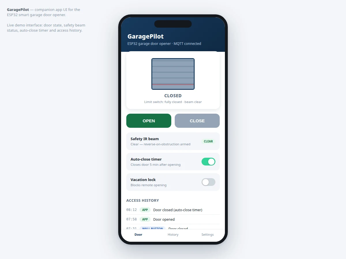
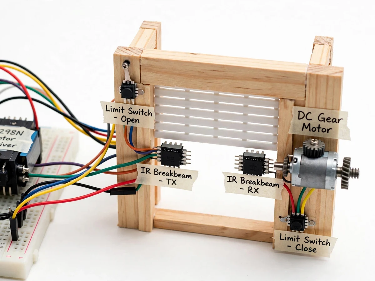
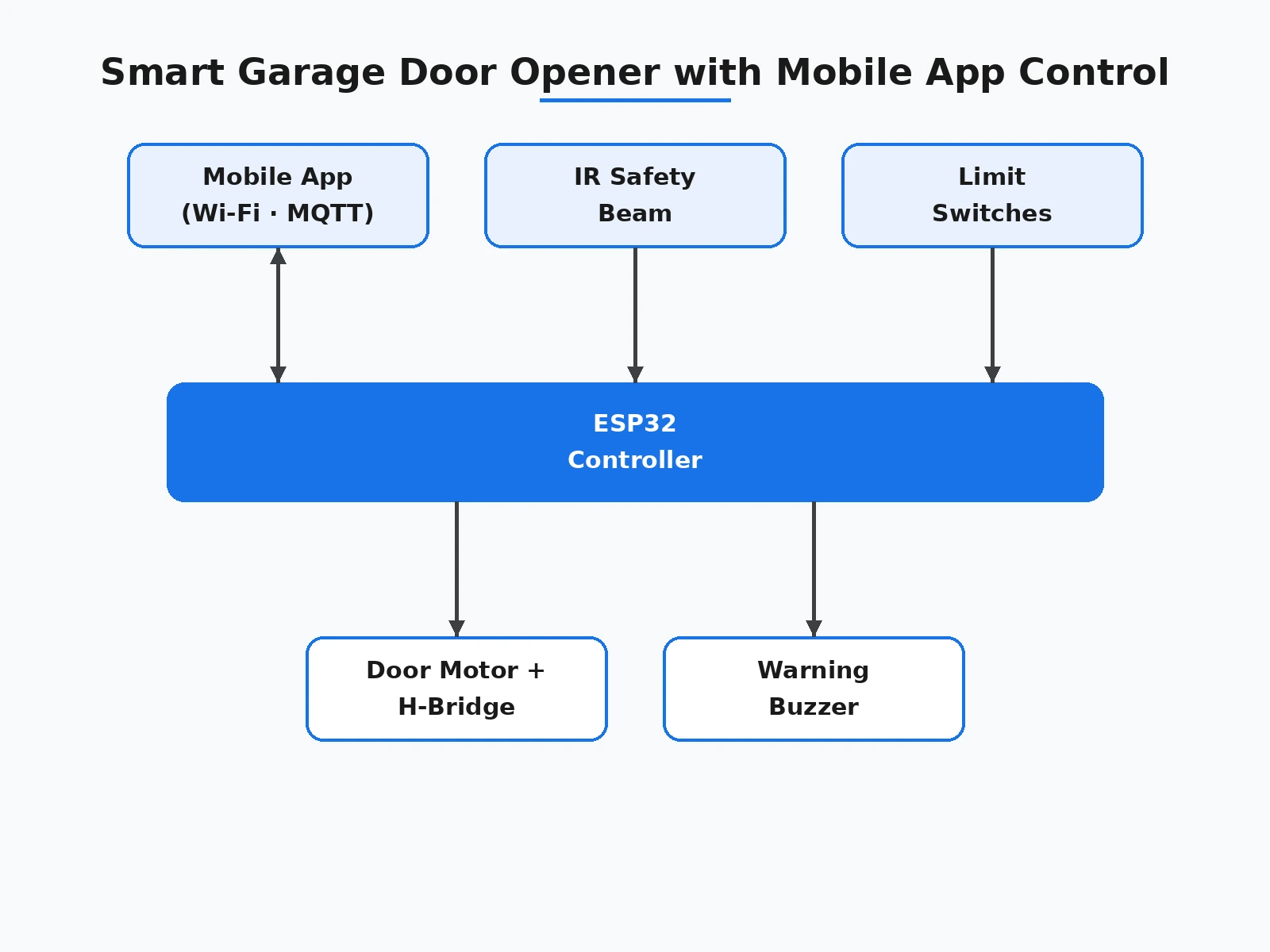
Garage door openers are a solved product — but the interesting engineering is in doing the safety logic right, and that is what this project demonstrates. An ESP32 controls a DC door motor through a relay/H-bridge driver with limit switches marking fully-open and fully-closed; commands come from a mobile-app UI over Wi-Fi/MQTT and from a physical wall button. The safety chain is the heart of the build: an IR break-beam across the doorway reverses a closing door immediately, motor current sensing detects a stalled/jammed door and cuts drive, and the app shows a live door state (OPEN / CLOSED / MOVING / OBSTRUCTED). An auto-close timer shuts an open door after a configurable interval, every operation is logged with timestamps, and a vacation mode disables remote opening. The scope is honest: demonstrated on a model garage door; the safety logic is the transferable engineering.
Opens or closes the door from the app, and receives obstruction, jam and timer alerts.
Follow the working sequence
How it works
- The user taps OPEN/CLOSE in the app; the command travels over Wi-Fi/MQTT to the ESP32, which checks the current door state from the limit switches.
- The controller drives the DC motor through the H-bridge/relay stage in the correct direction and tracks travel until the target limit switch engages.
- During closing, the IR beam is watched continuously; a break reverses the motor immediately and the app shows OBSTRUCTED.
- Current sensing watches for stall: abnormal current cuts the drive and raises a jam alert on the app and buzzer.
- If the door stays open past the configured auto-close interval, a warning beep sounds and the controller closes it automatically.
- Every operation is timestamped into the access log shown in the app; vacation mode blocks remote commands while leaving local safety logic armed.
Tech stack:
- ESP32 development board
- DC gear motor + H-bridge/relay driver stage
- Limit switches (open/closed position)
- IR break-beam safety sensor
- Motor current sensing (shunt/ACS-class)
- Mobile app UI over Wi-Fi/MQTT
- Wall push-button (local control)
- Arduino IDE (C/C++ firmware)
| Parameter | Value |
|---|---|
| Controller | ESP32, Wi-Fi/MQTT command path, local safety state machine |
| Drive | DC gear motor via H-bridge/relay stage; limit-switch positioned |
| Safety | IR break-beam reverse-on-obstruction; stall current cut; warning beep before auto-close |
| App UI | Open/close, live state, operation history, vacation mode, timer config |
| Auto-close | Configurable interval (design target default 5 min), warning beep first |
| Logging | Timestamped access log: command, source, result |
| Power | 12 V DC motor supply; 5 V DC logic |
Project features
- [Mobile app control] Companion app UI with open/close buttons, live door-state display and operation history, connected over Wi-Fi/MQTT — demonstrated as a working interface.
- [IR safety beam] Break-beam across the doorway reverses a closing door immediately and flags OBSTRUCTED in the app — the core safety feature.
- [Limit-switch positioning] Fully-open and fully-closed limit switches give the controller true position knowledge instead of timed guesses.
- [Stall detection] Motor current sensing cuts drive and raises a jam alert if the door stalls mid-travel.
- [Auto-close timer] A configurable timer closes an accidentally-left-open door, announced by a warning beep before motion.
- [Access logging] Every open/close command with source (app/button/timer) and timestamp is logged and shown in the app history.
- [Vacation lock mode] Disables remote opening while keeping the safety chain active — a realistic security feature.
What is included
- Working garage-door opener prototype (ESP32, DC gear motor + driver, limit switches, IR beam, current sensing, model door, wall button)
- Complete firmware source code (position control, safety chain, MQTT app link, auto-close, logging)
- Working mobile-app UI (open/close, live state, history, settings) demonstrated with the prototype
- Circuit and wiring documentation with motor-driver and safety notes
- Component list with ratings
- Safety-test and demo procedure guide
- Project report PDF (door-automation background, safety-chain design, methodology, test procedure)
- PPT presentation for final review
- Viva Q&A preparation document (H-bridge driving, limit sensing, safety interlocks, MQTT)
- Setup and demonstration guide
Limitations & prerequisites
- Demonstrated on a model garage door with a demo-scale motor; it is not installed on a real garage and is not a replacement for a certified opener.
- Safety logic is demonstrated at model scale; real-door forces, springs and entrapment standards are outside the project's scope.
- The app UI is demonstrated as a working interface; store deployment (Play Store/App Store) is not part of the build.
- Remote commands need Wi-Fi/internet; the wall button and safety chain work locally regardless.
- Motor sizing, current thresholds and auto-close timing are configured for the demo rig during the buyer's setup.
Frequently Asked Questions
How does the app control the door?
The app UI sends open/close commands over Wi-Fi/MQTT to the ESP32, which drives the DC motor through its driver stage; the app shows live door state and operation history.
What makes it safe?
An IR beam reverses a closing door on obstruction, current sensing cuts a stalled motor, limit switches give true position, and a warning beep precedes auto-close. The safety chain runs locally, independent of the network.
Is this for a real garage?
No — the prototype demonstrates the complete control and safety logic on a model door. Real-garage installation needs certified hardware and a professional installer.
What happens if the Wi-Fi drops?
The wall button and the entire safety chain keep working locally; only remote app commands are unavailable.
What are the main limitations?
Model scale, demo app UI (not a store app), network-dependent remote control, buyer-configured motor thresholds.
Is this project suitable for a final-year project?
Yes — for IoT and Embedded Systems programs. It combines motor control, safety interlocks, position sensing and app integration, all strong viva material. Suitable for B.E./B.Tech final-year projects in IoT and Embedded Systems.
Components & software requirements
- ESP32 development board
- DC gear motor + H-bridge/relay driver stage
- Limit switches (open/closed position)
- IR break-beam safety sensor
- Motor current sensing (shunt/ACS-class)
- Mobile app UI over Wi-Fi/MQTT
- Wall push-button (local control)
- Arduino IDE (C/C++ firmware)
Delivery information
Built-to-order project. Delivery timeline is shared after order confirmation based on current queue.
Support terms
Complete documentation, setup guide, and viva preparation included. Support for setup and explanation provided.
Download free synopsis (PDF)
Enter your name and WhatsApp number — the synopsis PDF downloads immediately. We may send occasional project updates on WhatsApp; no spam.