
More project photos (2)
The problem
Two-wheeler riders negotiate traffic with two mirrors and a shoulder check. Cars now ship blind-spot monitoring as standard, but motorcycles and scooters — most Indian vehicles — have no equivalent aid. A vehicle approaching from behind and slightly to the side sits where mirrors cannot see, and a backward glance costs attention on the road ahead. Riders therefore change lanes on guesswork, especially in mixed urban traffic where cars and trucks weave around two-wheelers.
This project builds a blind-spot aid at student scale: two HC-SR04 ultrasonic sensors on a rear mounting bracket scan the blind zones on both flanks, an Arduino Nano grades the threat by range, and small vibration motors on the handlebar grips warn the rider — left grip for a left-flank vehicle, right grip for the right — with pulses intensifying as it closes in. LED indicators give a visual backup. The build exercises ultrasonic ranging, embedded control logic, low-voltage regulation from a 12 V bike battery, and human-factors alert design — a rider-safety system a student can mount on a real two-wheeler for low-speed trials.
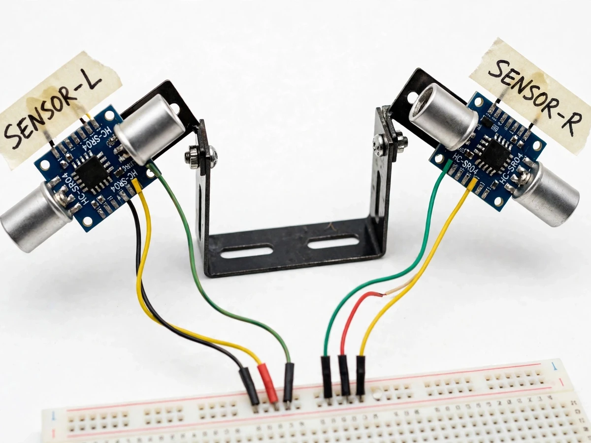
Left-side ultrasonic module covering the left rear blind zone.
Follow the working sequence
How it works
- The two HC-SR04 modules, angled about 20–30° outward from the rear axis on the tail bracket, each emit ultrasonic bursts and measure echo return time for their flank's blind zone.
- The Arduino Nano polls both sensors in sequence (approximately 10 readings per second per sensor, design target), converts echo time to distance in centimetres, and rejects out-of-range readings.
- Each flank's latest valid distance is compared against three configurable bands — far (design target ~2.5–4 m), near (~1.5–2.5 m) and critical (under ~1.5 m) — chosen for typical two-wheeler geometry and adjustable in firmware.
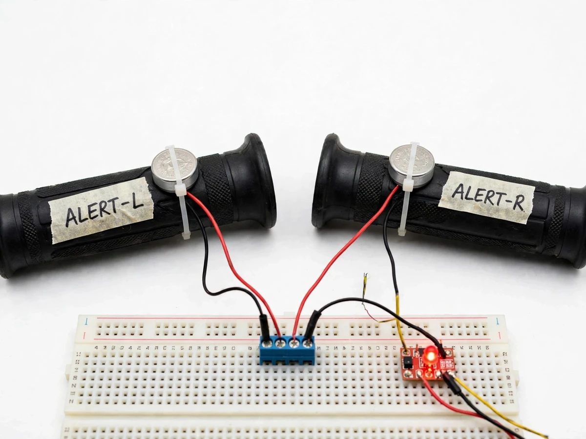
- The Nano drives the matching side's vibration motor: slow pulse (~1 Hz) in the far band, fast pulse (~4 Hz) in the near band, continuous ON in the critical band, while that side's mirror LED blinks or stays lit.
- If both flanks report a vehicle, both grips alert independently — the rider feels the direction as well as the urgency of each threat.
- A 12 V feed from the bike battery passes through the LM2596 buck converter (set to 5 V, expected high efficiency per the buck topology) to power the Nano, sensors and motors; a blade fuse and series diode guard against shorts and reverse connection.
- On power-up the firmware runs a self-check — each motor buzzes once and each LED flashes — confirming the full alert path before the first ride.
Tech stack:
- Arduino Nano (ATmega328P)
- HC-SR04 ultrasonic sensors ×2
- Embedded C (Arduino IDE)
- 3 V coin vibration motors
- LM2596 buck converter · 7805 regulator
- Amber mirror LED indicators
- 12 V bike-battery supply · blade fuse
- Breadboard · veroboard prototyping
| Parameter | Value |
|---|---|
| Controller | Arduino Nano (ATmega328P, 16 MHz) |
| Sensors | 2 × HC-SR04 ultrasonic (datasheet range 2 cm–400 cm, ~15° measuring angle) |
| Detection bands | Far ~2.5–4 m, near ~1.5–2.5 m, critical under ~1.5 m (design targets, firmware-configurable) |
| Alert outputs | 2 × 3 V coin vibration motors (one per grip) + 2 amber mirror LEDs |
| Sampling rate | Approximately 10 readings/s per sensor (design target) |
| Supply | 12 V DC bike battery; LM2596 buck to 5 V rail (expected) |
| Current draw | Approximately 250–400 mA with both motors on; under 100 mA idle (expected) |
| Alert latency | Under ~300 ms from detection to alert start (design target) |
| Bracket | Rear-mounted L-bracket, sensors angled 20–30° outward (configurable) |
| Operating temperature | 0–50 °C (component ratings, Approximate) |
Project features
- [Dual rear blind-zone sensing] Two HC-SR04 ultrasonic modules mounted on a rear bracket, angled outward to cover the left and right blind zones; each sensor is read independently so the system knows exactly which flank the vehicle is on.
- [Graded vibration alerts] The Nano drives the handlebar vibration motors with pulse patterns tied to distance bands — slow pulse for the far zone, fast pulse for the near zone, continuous vibration for the critical zone — with bands configurable in firmware.
- [Side-specific warning] A left-flank detection vibrates the left grip and lights the left mirror LED; a right-flank detection mirrors it — the rider feels both the direction and the urgency of the threat.
- [Mirror LED indicators] Amber LED indicators mounted near each mirror back up the vibration alert, useful when thick gloves or engine vibration mask the tactile cue.
- [12 V bike-battery power] The system runs from the two-wheeler's 12 V battery through an LM2596 buck converter to a clean 5 V rail; a blade fuse and reverse-polarity diode protect the build, and the feed is wired through the ignition switch.
- [Horn-bypass isolation] Alert circuits are wired on a completely separate path from the horn relay, so a fault or short in the alert wiring can never sound the horn or interfere with the bike's factory electrics.
- [Configurable zone bands] Distance thresholds, pulse rates and sensor sampling cadence are firmware constants, so the zones can be re-tuned for scooter versus motorcycle geometry during the calibration procedure.
What is included
- Assembled blind-spot prototype (rear sensor bracket, Arduino Nano, handlebar alert hardware) built to order
- Complete firmware source code (Embedded C, Arduino IDE)
- Circuit and wiring diagram with horn-bypass isolation notes
- Component list with exact part numbers and sourcing notes
- Calibration guide (zone-band tuning + road-trial procedure with results table to fill)
- Project report PDF (background, design, methodology, calibration)
- PPT presentation for the final review
- Viva Q&A preparation document (ultrasonic ranging, embedded control, power design)
Limitations & prerequisites
- Ultrasonic sensing needs line of sight: soft, sharply angled or highly absorbent surfaces return weak echoes, and heavy rain can degrade range — the HC-SR04's ~15° beam angle is a hard datasheet constraint on zone shape.
- The alert bands are design targets, not measured road results: detection range must be validated through the buyer-run road-trial procedure during calibration.
- The prototype is bench-proven on a breadboard; it is not sealed against water or road dust — a weatherproof enclosure is documented as future scope, not part of this build.
- At high speed, engine vibration can mask the tactile cue — above roughly 40 km/h the mirror LEDs become the primary alert (expected; to be confirmed in the rider trial).
- A poorly placed tail-lamp housing or luggage can partially block a sensor — the build guide includes a clear-line-of-sight mounting checklist for the bracket.
- This is a student safety prototype, not certified vehicle equipment: it must never be presented as a replacement for mirror checks or traffic rules.
Frequently Asked Questions
Which controller is used and why?
Arduino Nano (ATmega328P). It is compact enough for a two-wheeler mount, has enough digital pins for two HC-SR04 trigger/echo pairs plus motor and LED outputs, and its 5 V logic matches the sensors directly — no level shifting is needed.
How are the distance bands chosen?
Default bands are design targets for two-wheeler geometry (far ~2.5–4 m, near ~1.5–2.5 m, critical under ~1.5 m). They are firmware constants, and the calibration guide walks through re-tuning them with a tape measure and a parked car or a helper walking the blind zones.
Will it drain the bike battery?
Expected draw is roughly 250–400 mA with both motors vibrating and under 100 mA idle (expected values). The build guide recommends wiring the feed through the ignition switch so the system powers down with the bike, and a blade fuse protects the circuit.
Does it work in rain or at night?
Ultrasonic sensing is unaffected by darkness — a real advantage over camera-based aids, which struggle with headlight glare at night. Heavy rain can weaken echoes and reduce effective range, so the design is presented honestly as a dry-weather aid, with the LED indicators as backup.
Can it be fitted to any two-wheeler?
The bracket mounts near the tail lamp or number plate of most motorcycles and scooters with basic hand tools. Seat height and tail geometry vary, so the calibration procedure includes a mounting-position check for a clear sensor line of sight.
Is this project suitable for a final-year project?
Yes — for Electronics & Telecommunication and related programs. It demonstrates ultrasonic ranging, embedded C control logic, power regulation from a 12 V vehicle supply, and alert ergonomics, with rich viva material in sensor physics, firmware design and road-trial calibration. Suitable for B.E./B.Tech final-year projects in Electronics & Telecommunication, Electrical and IoT.
Components & software requirements
- Arduino Nano (ATmega328P)
- HC-SR04 ultrasonic sensors ×2
- Embedded C (Arduino IDE)
- 3 V coin vibration motors
- LM2596 buck converter · 7805 regulator
- Amber mirror LED indicators
- 12 V bike-battery supply · blade fuse
- Breadboard · veroboard prototyping
Delivery information
Built-to-order project. Delivery timeline is shared after order confirmation based on current queue.
Support terms
Complete documentation, setup guide, and viva preparation included. Support for setup and explanation provided.
Download free synopsis (PDF)
Enter your name and email — the synopsis PDF downloads immediately. We may send occasional project updates; no spam, unsubscribe anytime.