
More project photos (3)
The problem
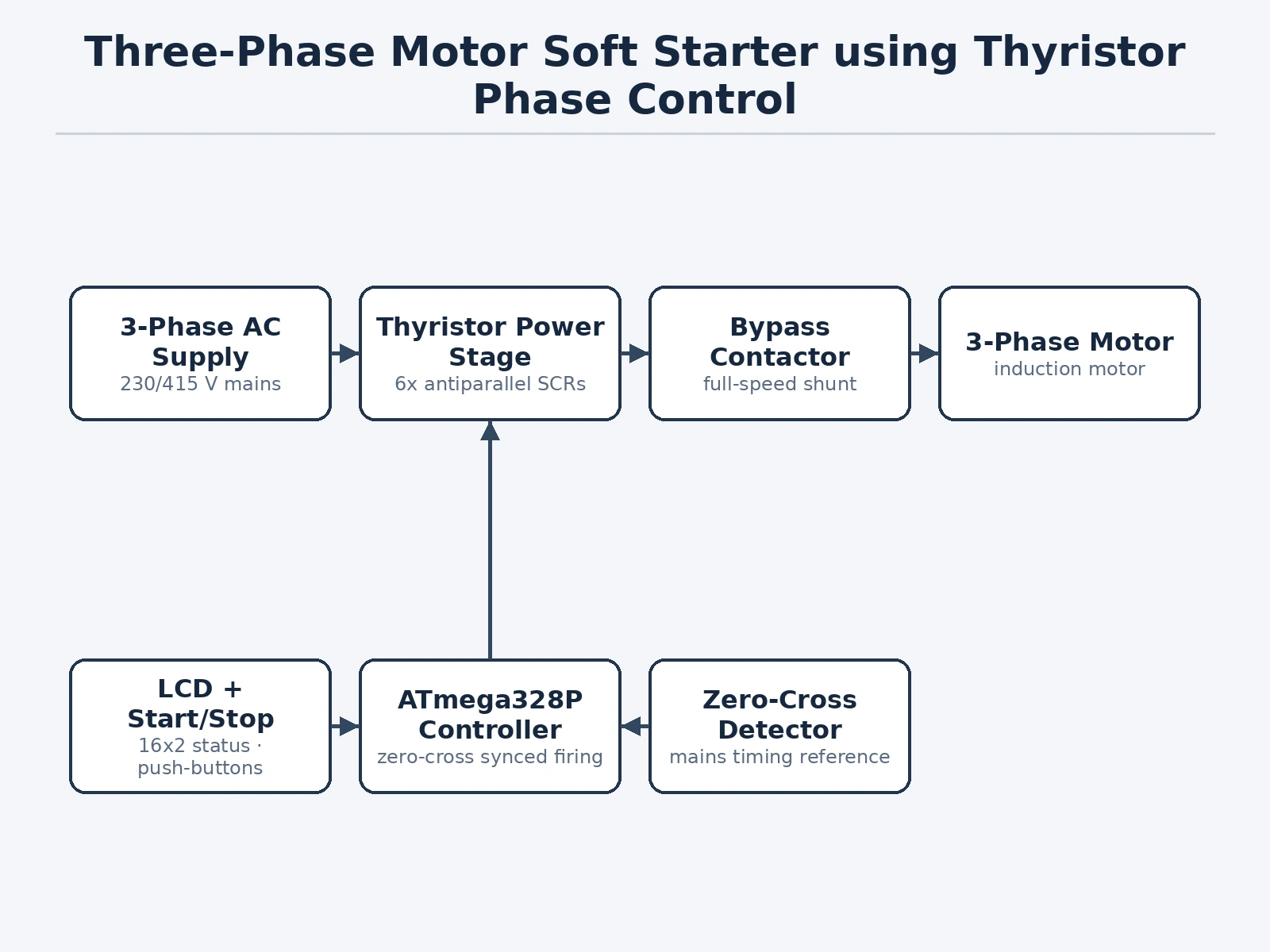
A three-phase induction motor switched directly onto the supply draws 5–7 times its rated current at start, stressing windings, couplings and the supply itself. The common student-lab answer is the star-delta starter, but it only steps the voltage down in two coarse stages — and the open-transition changeover produces its own current and torque transient. A soft starter solves this properly: it applies a continuously rising voltage ramp by chopping each mains half-cycle with semiconductor switches, so the motor accelerates smoothly with inrush limited to roughly 3–4 times full-load current. This project implements that as a real, demonstrable rig — six SCRs in three back-to-back pairs, a zero-crossing detector, an ATmega328P firing controller with adjustable ramp, and a bypass contactor that shorts the thyristors once the motor is up to speed. It is one of the clearest ways to see power electronics, control timing and machine behavior meet in a single build.
Optocoupler circuit gives the controller a clean timing reference on every mains half-cycle.
Follow the working sequence
How it works
- On start, the controller reads the zero-cross detector and begins firing each thyristor pair late in the half-cycle (large firing angle), so the motor sees only a fraction of the mains voltage.
- Over the set ramp time (approximately 1–10 s), the firing angle is progressively reduced, raising the RMS motor voltage smoothly toward full supply.
- The motor accelerates with inrush limited to approximately 3–4 times full-load current (design target), instead of the 5–7 times of a direct-on-line start.
- A current sensor on one phase reports the start current to the controller, shown live on the LCD; a persistent overcurrent latches a fault and drops the rig out.
- At the end of the ramp the controller closes the bypass contactor, shorting the thyristor pairs so running current flows through the contactor with negligible loss.
- On stop, the contactor drops out and the motor coasts down; the soft-stop option instead ramps the voltage back down before disconnecting.
- The emergency-stop button breaks the control circuit directly, independent of the microcontroller.
Tech stack:
- Back-to-back SCR pairs (3 phases) on heatsinks
- ATmega328P (Arduino Uno) firing controller
- Optocoupler zero-crossing detector
- 3-phase bypass contactor with 230 V coil
- Hall-effect current sensor
- 16×2 character LCD
- Snubber networks across each thyristor pair
- Start/stop/emergency-stop push-button station
| Parameter | Value |
|---|---|
| Supply | 3-phase, 400 V AC, 50 Hz (demo rig supply) |
| Demo motor | 3-phase induction motor, approximately 1–2 HP (design target) |
| Thyristors | 6 × SCR, 25 A / 600 V class (design selection) |
| Firing angle range | Approximately 0–180° per half-cycle |
| Ramp time | Approximately 1–10 s, adjustable (design target) |
| Starting current | Approximately 3–4 × full-load current (design target, not measured) |
| Control supply | 5 V DC regulated for controller and logic |
| Bypass | 3-phase contactor, closes at end of ramp |
| Display | 16×2 LCD: state, ramp time, line current |
Project features
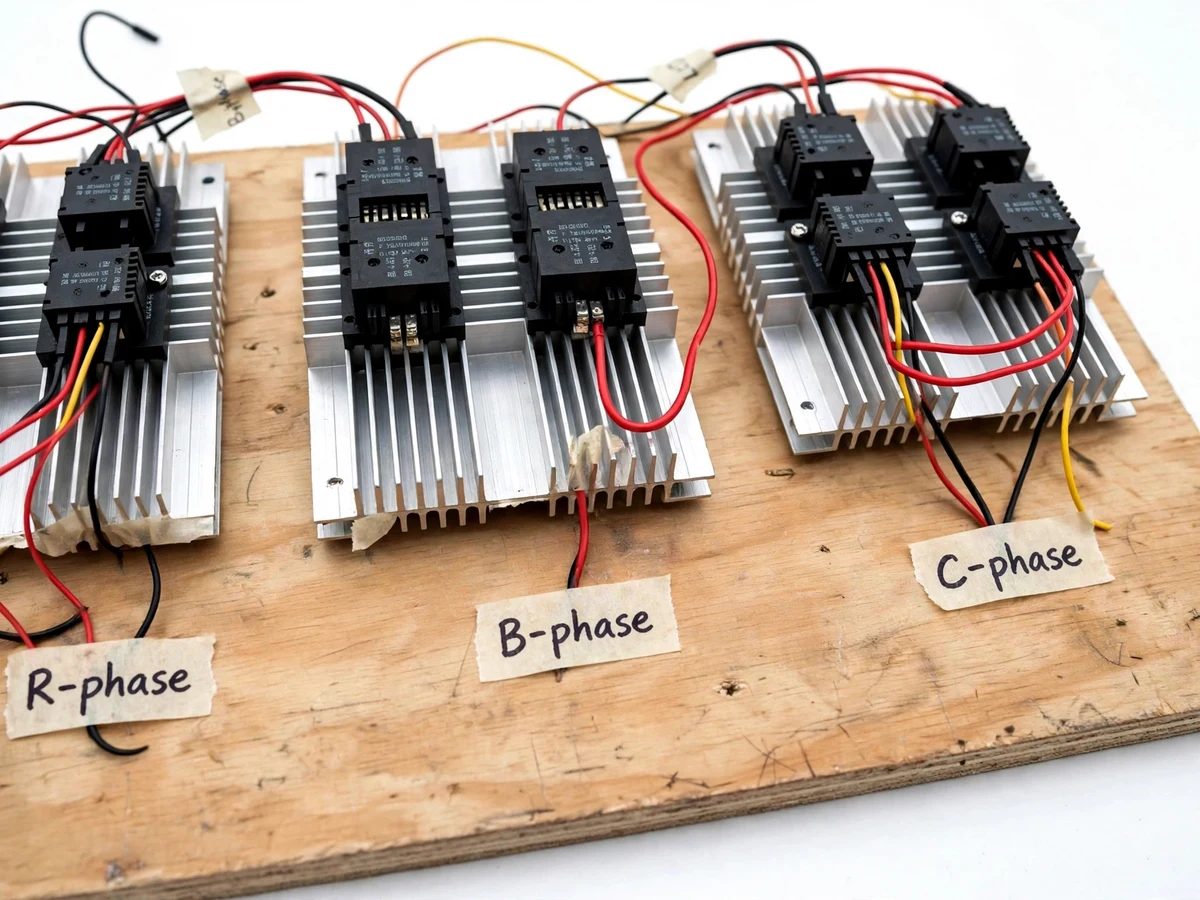
- [Back-to-back thyristor power stage] Two SCRs in antiparallel per phase (six total) on heatsinks, each pair conducting alternate half-cycles so the full three-phase supply is controllable.
- [Phase-angle firing control] The controller delays each thyristor's firing angle from near 180° (almost no voltage) down to 0° (full voltage), producing a smooth, stepless voltage ramp.
- [Adjustable ramp time] Start ramp settable from approximately 1 to 10 seconds with a potentiometer, plus a soft-stop (ramp-down) option for pump-type loads.
- [Zero-crossing detection] Optocoupler-based zero-cross detector gives the controller a clean timing reference on every half-cycle, so firing angles stay synchronized to the mains.
- [Bypass contactor at full speed] Once the ramp completes, a contactor shorts across the thyristor pairs, removing conduction losses and SCR heating during normal running.
- [LCD status display] 16×2 LCD shows ramp state (READY / RAMPING / RUNNING / FAULT), set ramp time and measured line current during start.
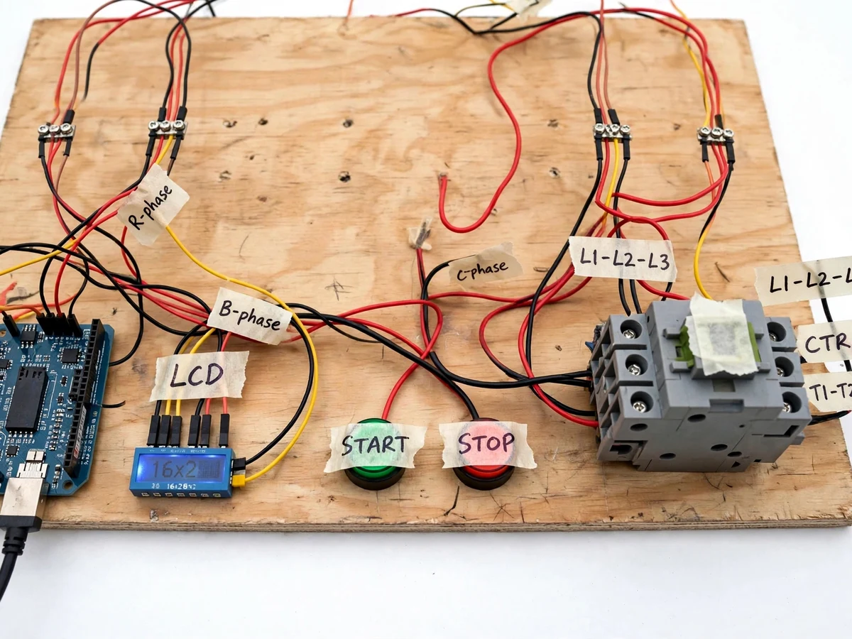
- [Start/stop station with emergency stop] Panel-mounted green start, red stop and latching emergency-stop push-buttons wired in the control circuit.
- [Current sensing on one phase] Hall-effect current sensor feeds the controller so start current is displayed and an overcurrent fault trips the rig safely.
What is included
- Complete thyristor power stage on heatsinks with snubbers and wiring
- ATmega328P firing controller with zero-cross detector and LCD
- Bypass contactor and start/stop/emergency-stop station, panel mounted
- Hall-effect current sensor and demo motor coupling arrangement
- Firmware source with firing-angle ramp tables
- Wiring diagram, thyristor selection and heatsink sizing notes
- Project report PDF, PPT presentation and viva Q&A document
Limitations & prerequisites
- This is a soft starter, not a variable-frequency drive — it controls starting/stopping only, with no running speed or torque control.
- Starting torque falls with the square of applied voltage, so high-inertia or fully-loaded starts may stall; the demo motor is sized accordingly.
- Phase-angle chopping injects harmonics into the supply during the ramp; it is a start-only phenomenon, not a running condition.
- The rig works on 400 V three-phase mains and must be operated under supervision with the enclosure closed; it is a lab demonstrator, not industrial switchgear.
- Heatsinks are sized for the start duty; extended repeated starts without cooling time can overheat the SCRs — a duty note is included.
- Start-current figures are design targets; the report documents the calibration procedure the student runs on their own build.
Frequently Asked Questions
How is this different from a star-delta starter?
Star-delta switches the motor between two fixed voltage steps (58% then 100%), with a transient at changeover. The soft starter raises the voltage continuously over a set ramp, so acceleration is smooth and inrush stays limited throughout the start.
Why are the thyristors bypassed at full speed?
A conducting thyristor drops about 1–1.5 V, which becomes heat at running current. Once the ramp finishes, the bypass contactor carries the current instead, so the SCRs only handle the short start interval.
What does the zero-crossing detector do?
Thyristor firing angles are measured from each mains zero crossing. The optocoupler detector gives the microcontroller a clean timing pulse every half-cycle so every firing instant stays synchronized to the supply.
Can it run the motor at reduced speed?
No. Reducing the firing angle permanently would overheat the motor and the SCRs and inject continuous harmonics. For speed control you need a VFD — this project is strictly about starting and stopping.
Is it safe to demonstrate?
The power stage is enclosed, the emergency stop breaks the control circuit directly, and overcurrent latches a fault. It runs on 400 V three-phase, so demonstrations are done with the enclosure closed and under supervision.
Is this project suitable for a final-year project?
Yes — for Electrical and Electronics programs. It combines power semiconductor devices, microcontroller timing, protection logic and machine behavior in one demonstrable rig. Suitable for B.E./B.Tech final-year projects in Electrical and Electronics engineering.
Components & software requirements
- Back-to-back SCR pairs (3 phases) on heatsinks
- ATmega328P (Arduino Uno) firing controller
- Optocoupler zero-crossing detector
- 3-phase bypass contactor with 230 V coil
- Hall-effect current sensor
- 16×2 character LCD
- Snubber networks across each thyristor pair
- Start/stop/emergency-stop push-button station
Delivery information
Built-to-order project. Delivery timeline is shared after order confirmation based on current queue.
Support terms
Complete documentation, setup guide, and viva preparation included. Support for setup and explanation provided.
Download free synopsis (PDF)
Enter your name and WhatsApp number — the synopsis PDF downloads immediately. We may send occasional project updates on WhatsApp; no spam.