
More project photos (3)
The problem
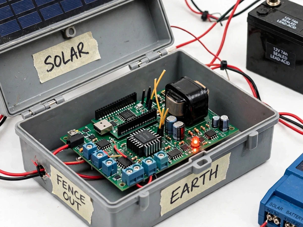
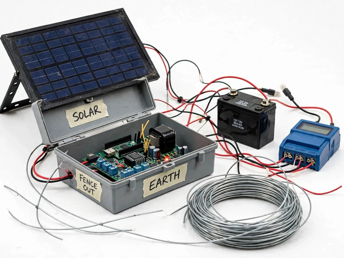
Farmers on the edges of forests and scrubland lose standing crops every season to nilgai, wild boar and stray cattle that push through field boundaries at night. Mains power rarely reaches these field edges, so conventional electric fencing — which needs a reliable AC supply for its energizer — is simply not an option for smallholders. This project builds a solar-powered electric fence energizer that runs entirely off-grid: a photovoltaic panel charges a 12 V battery through a charge controller, and a timer-driven flyback stage converts that stored energy into short, high-voltage, energy-limited pulses delivered to the fence wire about once per second. Each pulse is a sharp deterrent shock, not a continuous current, so the design stays non-lethal while still teaching animals to avoid the boundary. A fault-indication circuit watches the fence line continuously and raises a visible and audible alarm when vegetation shorts the wire or a break interrupts it. The build is a complete lesson in power electronics, pulse transformers and rugged outdoor field hardware.
20 W solar panel that charges the 12 V battery through the PWM charge controller.
Follow the working sequence
How it works
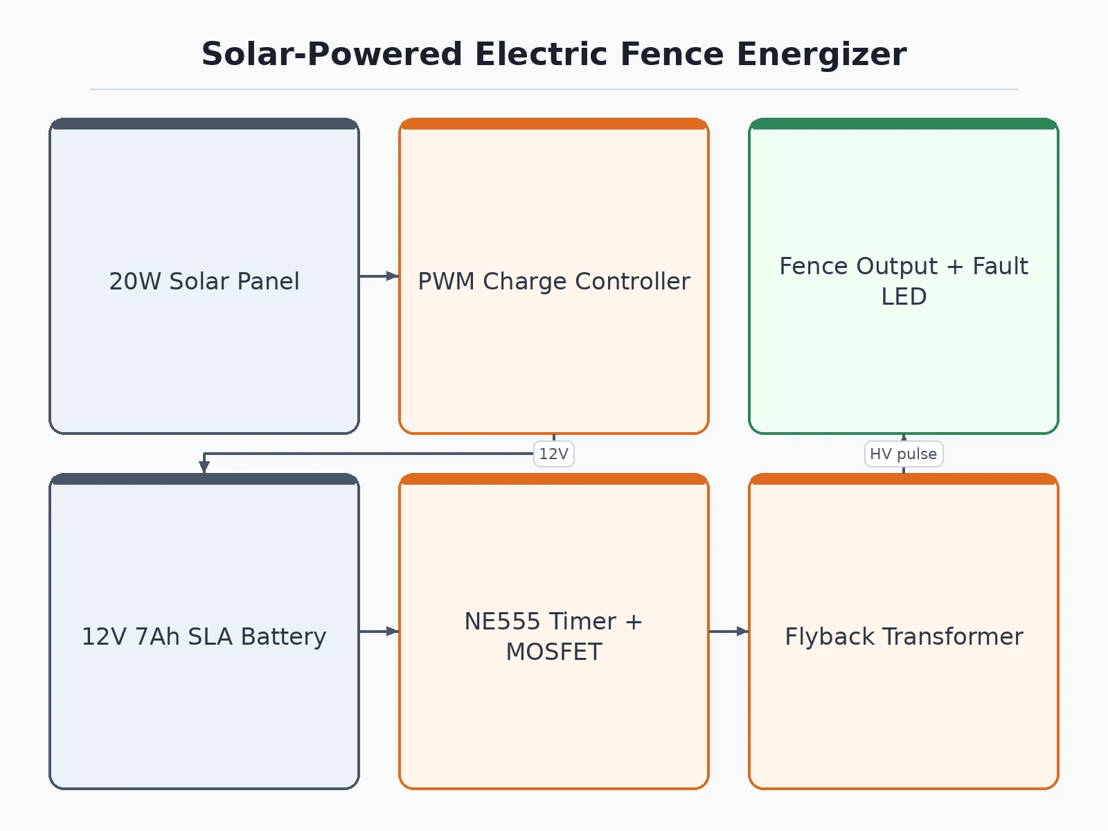
- The solar panel charges the 12 V battery through the PWM charge controller; status LEDs show panel-charging, battery-full and low-battery conditions.
- A timing stage (NE555/Arduino-based, approximately 1 Hz) switches a MOSFET that drives the flyback transformer primary, storing magnetic energy each cycle.
- On switch-off, the transformer secondary releases the stored energy as a short high-voltage pulse onto the fence wire, limited to a design-target fraction of a joule.
- An animal touching the wire completes a path through the ground back to the earth stake and receives a brief deterrent shock; the pulse is too short to sustain current.
- A sensing circuit continuously monitors fence-line loading: a short to ground or a broken wire moves the sensed level beyond the set threshold.
- On a detected fault, the controller lights the red fault LED and sounds the buzzer until the line is restored and the fault is acknowledged.
- If the battery falls below the low-voltage cutoff, pulse generation is inhibited and the low-battery LED warns the user, resuming automatically after the panel recharges.
Tech stack:
- 20 W solar panel · 12 V
- 10 A PWM charge controller
- 12 V · 7 Ah SLA battery
- NE555 timer · Arduino Nano
- Flyback transformer · MOSFET driver
- Analog comparator fault sensing
- Weather-resistant enclosure · earthing terminal
- Status LEDs · buzzer
| Parameter | Value |
|---|---|
| Solar panel | 20 W, 12 V nominal (datasheet) |
| Charge controller | 10 A PWM, 12 V (datasheet) |
| Battery | 12 V, 7 Ah sealed lead-acid (datasheet) |
| Pulse energy | Approximately 0.2–0.5 J per pulse (design target, energy-limited) |
| Pulse repetition | Approximately 1 pulse per second (design target) |
| Peak output voltage | Approximately 6–8 kV open-circuit (design target; verified by buyer on own build) |
| Pulse width | Tens of microseconds (design target) |
| Fault indication | Red LED + buzzer on short-to-ground or wire break |
| Charging indicators | Panel-charging, battery-full and low-battery LEDs |
| Low-voltage cutoff | Approximately 10.5–11 V (design target, protects the battery) |
| Expected runtime | Approximately 2–3 nights per full charge without sun (expected, load-dependent) |
| Enclosure | Weather-resistant box with earthing terminal and cable glands (design target) |
| Fence coverage | Up to approximately 500 m of single wire (design target; depends on wire, vegetation and earthing) |
Project features
- [Off-grid solar power] A 20 W photovoltaic panel and a 12 V 7 Ah sealed lead-acid battery, managed by a 10 A PWM charge controller, run the energizer through the night with no mains supply at the field edge.
- [Energy-limited pulse output] A timer-driven flyback stage fires short high-voltage pulses at about one per second; the stored energy per pulse is a design-target fraction of a joule, so the shock deters without sustaining current.
- [Fence fault indication] A sensing circuit detects a wire shorted to ground or a broken line and drives a red LED plus a buzzer, so the farmer locates the fault instead of walking the whole boundary.
- [Solar charging status LEDs] Separate indicators show panel charging, battery full and low-battery states, giving an at-a-glance health check of the power side of the system.
- [Earthing terminal and enclosure] The control box carries a dedicated earth terminal for the mandatory fence earth stake, and the enclosure is specified for outdoor mounting with cable glands for the panel, fence and earth leads.
- [Adjustable pulse rate and drive] Pulse repetition and drive duty are set through firmware/potentiometer presets, so the student can demonstrate the trade-off between deterrent strength and battery drain on the viva table.
- [Trimmable fault threshold] The short-detection comparator trip point is adjustable, so the builder can calibrate sensitivity against the local fence length and vegetation load during installation.
- [Low-battery lockout] The controller inhibits pulse generation when the battery drops below the cutoff, protecting the sealed lead-acid battery from deep discharge and resuming automatically after the panel recharges.
What is included
- Working energizer prototype (control box, solar panel, battery, charge controller, earth-stake terminal)
- Firmware for the timing and fault logic, with calibration notes
- Circuit and wiring documentation (schematic, PCB layout, earthing guide)
- Component list with the exact part numbers used in the build
- Fence installation and safety procedure sheet
- Project report PDF, PPT presentation and viva Q&A document
- Project abstract PDF
Limitations & prerequisites
- High-voltage safety: the output is energy-limited by design (fractions of a joule, design target) and non-lethal as a deterrent, but proper earthing is mandatory and warning signage must be fixed on every fenced stretch — never build or demo the fence without the earth stake connected.
- Not certified: this is an academic prototype, not tested to IEC 60335-2-76 (the safety standard for electric fence energizers); it must not be presented or sold as a certified agricultural product.
- Regulatory check required: electric fencing rules vary by state and locality — this is not for urban or residential use without confirming local regulations first.
- Output voltage and pulse energy are design targets; the buyer verifies them on their own build with a fence tester following the provided procedure — no measured values are claimed.
- Coverage depends on wire type, vegetation load and earthing quality; heavy wet vegetation can load the fence and reduce the effective range.
- Keep children, pets and bystanders clear of the live wire; disconnect and fully discharge the fence before any maintenance.
Frequently Asked Questions
Is this project suitable for a final-year project?
Yes — for Electrical, Electronics and E&TC programs. It combines solar power electronics, pulse-transformer design, analog fault sensing and embedded timing in one demonstrable build, and the report explains each stage so the student can defend it confidently in the viva.
Is the fence safe to touch?
The design is energy-limited: each pulse carries a fraction of a joule for only tens of microseconds, which is a deterrent shock rather than a continuous current. Safe use still demands proper earthing, warning signs on every stretch, and keeping the fence away from public paths and children.
Does it work without sunlight?
Yes — the 12 V 7 Ah battery runs the energizer through the night and across overcast days, approximately 2–3 nights per full charge (expected, load-dependent). The panel recharges it during the day, and LEDs show the charging state at a glance.
Can the pulse rate or strength be changed?
Pulse repetition and drive duty are adjustable through firmware and potentiometer presets, so the student can demonstrate the trade-off between deterrence and battery life. The per-pulse energy stays capped by the flyback design regardless of settings, so every configuration remains safe to demonstrate on the viva table.
What power supply does the installation need?
None beyond sunlight — the panel, charge controller and battery form a complete off-grid supply. For the indoor viva demo, a bench 12 V supply can substitute for the panel and battery so the pulse stage is shown without energizing a fence line.
What will I receive with the project?
The working prototype — control box, solar panel, battery and charge controller — plus the timing and fault firmware, circuit and wiring documentation, a fence safety and installation sheet, the project report, PPT, complete viva Q&A and the abstract PDF.
Components & software requirements
- 20 W solar panel · 12 V
- 10 A PWM charge controller
- 12 V · 7 Ah SLA battery
- NE555 timer · Arduino Nano
- Flyback transformer · MOSFET driver
- Analog comparator fault sensing
- Weather-resistant enclosure · earthing terminal
- Status LEDs · buzzer
Delivery information
Built-to-order project. Delivery timeline is shared after order confirmation based on current queue.
Support terms
Complete documentation, setup guide, and viva preparation included. Support for setup and explanation provided.
Download free synopsis (PDF)
Enter your name and email — the synopsis PDF downloads immediately. We may send occasional project updates; no spam, unsubscribe anytime.