
More project photos (2)
The problem
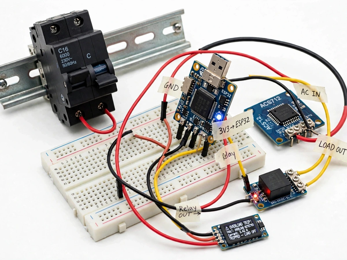
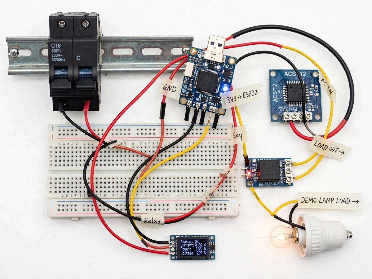
A conventional miniature circuit breaker protects a circuit silently — it trips on thermal-magnetic action, but it gives no reading of how much current is flowing, no warning before the trip, and no way to switch or reset it from another room. Students study overload protection in theory but rarely see the sensing-to-trip chain instrumented: current measured, RMS computed, threshold compared, and a switching element opened, all visible and adjustable. This project builds that chain as a working prototype. Load current flows through an ACS712 hall-effect current sensor placed in series with a commercial C16 MCB; an ESP32 samples the sensor, computes true RMS current, shows live current and estimated power on an OLED, and drives a relay module that drops the load when a configurable overload threshold is crossed for a sustained window. Because the ESP32 has Wi-Fi, the same unit hosts a small web dashboard for remote trip, reset, threshold adjustment and a timestamped trip-event log. The relay trip is an electronic demonstration layer — the commercial MCB stays in the circuit for its own conventional protection, and the prototype is explicitly not certified switchgear.
Hall-effect module in series with the load; outputs 185 mV per amp.
Follow the working sequence
How it works
- The 230 V AC demo-branch load current flows through an ACS712-5A hall-effect sensor module (185 mV/A sensitivity — datasheet) wired in series with the commercial C16 MCB.
- The ESP32 samples the sensor output with its 12-bit ADC at approximately 2,000 samples per second and computes true RMS current over each mains cycle window.
- The OLED displays the live RMS current, estimated apparent power (nominal 230 V, configurable), and the current relay/MCB state.
- Firmware compares the RMS value against the configured threshold (default 5 A, adjustable 0.5–10 A); if it stays above the threshold for 3 consecutive measurement windows, the ESP32 de-energizes the relay, opening the load circuit (design target: trip actuation within ~200 ms of a sustained breach).
- The ESP32's embedded web server, reachable over 2.4 GHz Wi-Fi, shows the same readings plus a trip-event log with timestamps.
- From the dashboard you can force a remote trip, reset the relay after a trip, change the threshold, and run the calibration routine — every action is logged.
- Manual recovery is always available: the relay can be reset from the dashboard or a physical push button, and the MCB's own handle remains the physical isolation point.
Tech stack:
- ESP32
- ACS712 hall current sensor
- Relay module (10 A)
- OLED display · SSD1306
- Arduino IDE
- Embedded web server (ESPAsyncWebServer)
- C16 single-pole MCB (commercial, unmodified)
| Parameter | Value |
|---|---|
| Controller | ESP32, dual-core, 3.3 V logic |
| Current sensor | ACS712-5A: ±5 A range, 185 mV/A sensitivity (datasheet) |
| ADC sampling | 12-bit, approximately 2 kSa/s on the sensor channel (expected) |
| Overload threshold | 0.5–10 A, firmware and dashboard configurable; default 5 A |
| Trip element | Relay module, 10 A at 250 VAC (datasheet), driven by ESP32 |
| Trip response | Design target: under ~200 ms from a sustained threshold breach |
| Branch breaker | Commercial C16 single-pole MCB (certified part; in demo wiring, unmodified) |
| Mains | 230 V AC, 50 Hz demo branch |
| Display | 0.96-inch OLED, live current / power / relay status |
| Connectivity | Wi-Fi 2.4 GHz, embedded web dashboard |
| Power | 5 V DC isolated supply for ESP32, sensor, relay and display; demo lamp load as supplied |
| Reset | Dashboard button + physical push button |
Project features
- [Overload trip via relay] The ESP32 monitors RMS load current and opens a 10 A relay in series with the load when the configurable threshold is crossed for a sustained debounce window — a visible, instrumented overload trip you can demonstrate on demand.
- [Live current & power readout] A 0.96-inch OLED shows real-time RMS current, estimated apparent power (computed from a configurable nominal 230 V) and relay status, updating several times per second.
- [Configurable trip threshold] The overload limit is adjustable from 0.5 A to 10 A through the dashboard or a firmware constant, so different demo loads and trip scenarios can be set up for the viva.
- [Remote trip and reset over Wi-Fi] The ESP32 hosts an embedded web dashboard with Trip and Reset buttons; a trip command opens the relay and a reset command closes it again, logged with timestamps.
- [Trip event log] Every automatic trip, remote trip and reset is recorded with date and time in the dashboard, giving examiners a clean cause-and-effect record of the demonstration.
- [Calibration mode] A dashboard routine lets you calibrate the sensor against a known load so the displayed current matches a clamp meter — the calibration constant is stored and documented in the report.
- [Commercial MCB in the loop] A real C16 MCB stays in the branch wiring as the conventional protection element, so the build honestly demonstrates a smart layer added around standard switchgear rather than replacing it.
What is included
- Working Smart MCB prototype (ESP32, ACS712 module, relay module, OLED, C16 MCB on DIN rail, wired demo lamp load)
- Complete firmware source with comments (current sensing, RMS computation, trip logic, web dashboard)
- Wiring diagram and component list
- Safe testing procedure and calibration notes
- Project report PDF (background, protection concepts, methodology, results)
- PPT presentation for final review
- Viva Q&A preparation document (overload vs short circuit, RMS measurement, MCB curves, relay vs contactor, mains safety)
Limitations & prerequisites
- The prototype is a demonstration add-on, not certified switchgear: it does not replace a certified MCB, does not implement standard trip curves (I²t) or discrimination, and must never be presented as rated protection equipment.
- The electronic trip layer cannot protect against bolted short circuits the way a real MCB's magnetic element does — short-circuit protection still comes only from the commercial MCB.
- The ACS712-5A module measures up to ±5 A (datasheet); demo loads must stay within the sensor and relay ratings, and accuracy depends on the calibration routine.
- Mains wiring is hazardous: the prototype is assembled and tested by the Projectech team, and students must not modify mains-side wiring without qualified supervision.
- Remote trip over Wi-Fi is a convenience feature, not a safety interlock — it must never be relied on for personnel protection, and the MCB handle stays the physical isolation point.
- Wi-Fi range and reliability depend on the local network; all local functions (sensing, OLED, threshold trip) work without Wi-Fi.
Frequently Asked Questions
Is this project suitable for a final-year project?
Yes — for Electrical and Electronics programs. It demonstrates AC current sensing, RMS computation on a microcontroller, relay-based trip logic, calibration against a reference meter, and a Wi-Fi dashboard, all tied together around the real concept of overload protection.
Which controller and sensor are used?
An ESP32 (for Wi-Fi and fast ADC sampling) and an ACS712-5A hall-effect current sensor module (±5 A, 185 mV/A per its datasheet).
Does it work without Wi-Fi?
Yes for all protection functions — current sensing, the OLED readout and the automatic overload trip are local. Remote trip/reset, the event log and threshold changes need the Wi-Fi dashboard.
How does the trip differ from a normal MCB trip?
A normal MCB trips thermally or magnetically inside sealed, certified hardware. This project's electronic trip is an extra, visible layer: the ESP32 measures current and opens a relay on overload. The commercial MCB stays in the circuit for its own conventional protection.
Can the overload threshold be changed?
Yes — from 0.5 A to 10 A through the dashboard or a firmware constant, so you can demo trips on different loads during the viva.
What are the main limitations?
It is a demonstration prototype, not certified switchgear; it does not implement standard I²t trip curves and cannot clear bolted short circuits itself. Mains-side wiring must be treated with full electrical safety discipline.
Components & software requirements
- ESP32
- ACS712 hall current sensor
- Relay module (10 A)
- OLED display · SSD1306
- Arduino IDE
- Embedded web server (ESPAsyncWebServer)
- C16 single-pole MCB (commercial, unmodified)
Delivery information
Built-to-order project. Delivery timeline is shared after order confirmation based on current queue.
Support terms
Complete documentation, setup guide, and viva preparation included. Support for setup and explanation provided.
Download free synopsis (PDF)
Enter your name and email — the synopsis PDF downloads immediately. We may send occasional project updates; no spam, unsubscribe anytime.