
More project photos (3)
The problem
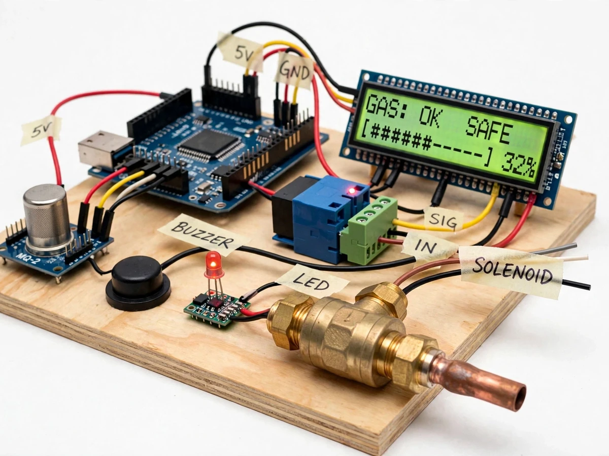
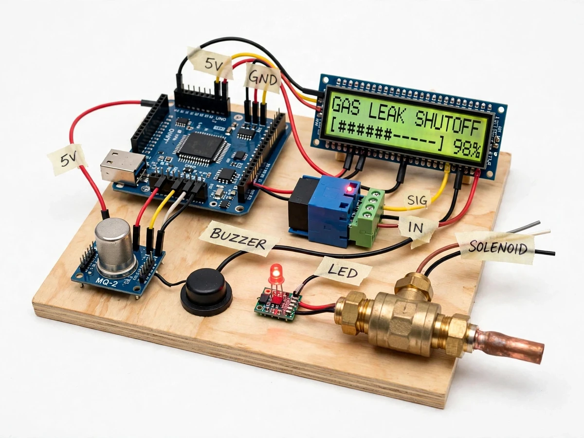
Smart Gas Leakage Detector with Automatic Valve Shutoff is a standalone LPG/PNG safety device built around an MQ-2 gas sensor and an Arduino controller. Unlike a monitoring gadget that only warns, this device acts: on detecting a leak it sounds a buzzer, flashes a red LED, and — most importantly — de-energizes a relay that lets a normally-closed 12 V solenoid valve in the gas line slam shut, cutting the fuel supply, while switching on an exhaust fan to ventilate the room. LPG leaks from regulators, hoses and stove fittings fill kitchens silently, and LPG's lower explosive limit is only about 1.8–2.0% by volume (18,000–20,000 ppm), so a dangerous concentration can build near the floor — where LPG pools — before anyone smells the odorant. This device is a pure safety actuator — it acts, not just alerts — and stands clearly apart from weight-based LPG booking monitors.
Heated tin-dioxide element drops in resistance in combustible gas; the module feeds an analog voltage to the Arduino.
Follow the working sequence
How it works
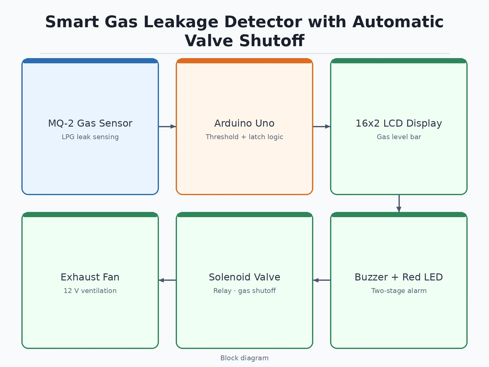
A leak in the air reaches the MQ-2 sensor, whose heated tin-dioxide (SnO2) element drops in electrical resistance in the presence of combustible gas, changing the analog voltage the Arduino reads. The firmware compares this reading against the configured alarm threshold roughly ten times per second: below it, the LCD shows the live gas-level bar and the valve stays open; above it, a two-second confirmation filter rejects momentary spikes such as cooking smoke. On confirmation the controller executes the safety sequence end to end — the buzzer sounds, the red LED flashes, the LCD shows the leak warning, the valve relay de-energizes so the normally-closed solenoid valve shuts the gas line, and the exhaust fan starts. The fault then latches: even if the gas clears, the valve remains shut and the alarm stays on until the user presses the manual reset button, which re-arms the system only after the reading has fallen back below the safe threshold.
- The MQ-2 sensor's heated SnO2 element changes resistance in combustible gas; the Arduino reads the resulting analog voltage on an analog pin.
- Firmware converts the reading to a gas-level percentage and updates the 16×2 LCD bar about ten times per second during normal monitoring.
- If the reading crosses the alarm threshold (approximately 10% of LPG LEL, adjustable), a confirmation timer runs for about 2 s (design target) to reject transient spikes like cooking smoke.
- On confirmation, the buzzer sounds, the red LED flashes, and the LCD switches to the leak warning display.
- The controller de-energizes the 5 V relay, closing the normally-closed 12 V solenoid valve in the gas line within approximately 5 s of confirmed detection (design target), cutting off the supply.
- The second relay contact starts the exhaust fan to ventilate the room, since LPG pools near the floor.
- The fault latches: the valve stays shut and the alarm continues even after the gas clears, until the reset push button is pressed with the reading back below the safe threshold.
Tech stack:
- Arduino Uno (ATmega328P)
- MQ-2 / MQ-6 gas sensor module
- 12 V DC normally-closed solenoid valve + 5 V relay modules
- Arduino IDE (C/C++ firmware)
- 16×2 character LCD
- 5 V active buzzer, red LED, reset push button
- 12 V DC exhaust fan + relay output
- 12 V DC adapter + buck converter (5 V logic supply)
| Parameter | Value |
|---|---|
| Controller | Arduino Uno (ATmega328P) |
| Gas sensor | MQ-2 (or MQ-6 LPG variant); datasheet detection range 300–10,000 ppm LPG |
| Sensing element | Heated SnO2 (tin dioxide); heater draws approximately 150–180 mA at 5 V (datasheet, max 900 mW) |
| LPG lower explosive limit | Approximately 1.8–2.0% by volume (18,000–20,000 ppm), standard reference value |
| Alarm threshold | Approximately 10% of LPG LEL (design target, firmware-adjustable) |
| Confirmation delay | Approximately 2 s before tripping (design target, rejects transient spikes) |
| Valve shutoff response | Valve closes within approximately 5 s of confirmed detection (design target) |
| Solenoid valve | 12 V DC, normally closed; for the low-pressure gas line downstream of the cylinder regulator (approximately 2.75 kPa domestic) |
| Valve relays | 5 V relay modules, 10 A / 250 V AC contacts (datasheet) |
| Display | 16×2 LCD with gas-level bar and status text |
| Alarm outputs | 5 V active buzzer + red LED |
| Exhaust fan | 12 V DC fan via second relay contact (design target) |
| Manual reset | Latching fault — valve stays shut until reset pressed with reading below safe level |
| Power | 12 V DC, 2 A adapter; buck converter to 5 V for logic and sensor |
Project features
The Smart Gas Leakage Detector is defined by one idea: detection is not enough — the system must physically remove the hazard. Its four defining capabilities are the automatic solenoid valve shutoff that cuts the gas line within seconds of a confirmed leak, the two-stage local alarm (buzzer plus LED plus an LCD gas-level bar) so occupants know exactly what is happening, the exhaust-fan trigger that ventilates the room instead of letting gas pool, and the latching fault logic that keeps the valve shut until a human presses the reset button — no silent auto-recovery while a leak may still exist. Around this core the project teaches real interfacing work: analog sensing from a heated SnO2 element, relay driving with isolation, 12 V actuation from logic power, and threshold tuning against the sensor's ppm response curve.
- [Automatic solenoid valve shutoff] On a confirmed leak the Arduino de-energizes a 5 V relay that lets a normally-closed 12 V solenoid valve in the gas line close, physically cutting the gas supply. Valve closure within approximately 5 s of confirmed detection is the design target.
- [MQ-2 gas sensing with LCD level bar] The MQ-2 sensor (datasheet detection range 300–10,000 ppm LPG) feeds an analog input; firmware maps it to a percentage bar on the 16×2 LCD so the gas concentration is visible before the alarm threshold is reached.
- [Two-stage alarm] Crossing the warning threshold sounds a 5 V buzzer and flashes a red LED; the LCD switches to a leak warning. The alarm threshold is set around 10% of LPG's lower explosive limit and is adjustable in firmware.
- [Exhaust fan trigger] A second relay contact starts a 12 V exhaust fan on leak detection to ventilate the room, since LPG is heavier than air and pools near the floor.
- [Latching fault with manual reset] Once tripped, the system holds the valve shut and the alarm on until the reset push button is pressed — it never re-opens the gas line on its own after the air clears.
- [Sensor fault supervision] Firmware checks for an open or shorted sensor reading at power-on and flags a sensor fault instead of silently staying unarmed.
- [Adjustable thresholds] Alarm and shutoff thresholds, confirmation delay and fan run-on time are all set in one configuration section of the firmware, documented for the viva.
What is included
- Working prototype: Arduino controller board, MQ-2 sensor module, 12 V normally-closed solenoid valve with gas-line fittings, 5 V relay modules, buzzer and red LED alarm, 16×2 LCD, exhaust-fan output terminal, manual reset button — all mounted on a demo base
- Complete Arduino firmware (C++) with threshold logic, confirmation delay, latching fault, fan control and LCD display
- Wiring diagram and full component list
- Sensor threshold calibration procedure (buyer-run, with the included setup method)
- Project report PDF (10-section), PPT presentation and viva Q&A document
Limitations & prerequisites
- Academic prototype, not certified gas-safety equipment: it must never replace a certified LPG leak detector or a licensed gas fitter's installation — say this explicitly in the report and viva.
- The MQ-2 is cross-sensitive: cooking smoke, cigarette smoke and alcohol vapour can raise the reading, so the sensor must be mounted away from the stove and thresholds tuned during setup; false alarms are possible.
- The solenoid valve suits only the low-pressure line downstream of the cylinder regulator (approximately 2.75 kPa for domestic LPG) — never the high-pressure cylinder connection.
- Leak demonstrations with real LPG must be done outdoors or in a ventilated area under supervision; never release gas indoors to "test" the device.
- The sensor needs an initial aging of approximately 24 h (datasheet guidance) before threshold calibration, plus about 20–30 s of warm-up at every power-on.
- No battery backup and no remote alerts in the base build; GSM/Wi-Fi alert extensions are available as customizations.
- It cannot detect leaks that occur before the valve's position on the line — the solenoid must sit downstream of the regulator, upstream of the hose and stove joints it protects.
Frequently Asked Questions
How is this different from an LPG cylinder monitor with leak detection?
This is a safety actuator, not a monitor. The published LPG cylinder monitor tracks cylinder weight for booking alerts, with leak detection as a side feature; this device physically cuts the gas line through a solenoid valve, sounds an alarm and ventilates the room when a leak is confirmed. There is no weight sensing, no booking logic and no cloud dashboard.
How does the sensor actually detect the gas?
The MQ-2's heated tin-dioxide (SnO2) element drops in resistance when combustible gases like propane and butane reach it; the module turns that into an analog voltage the Arduino reads. The heater needs about 20–30 s of warm-up at each power-on, and a fresh sensor should be aged roughly 24 h before you calibrate the alarm threshold.
Which controller is used and why?
An Arduino Uno. The whole system is offline logic — one analog read, threshold comparison and digital outputs — so no Wi-Fi or cloud is needed; reliability matters more than connectivity in a safety device. The firmware, wiring and threshold tuning are simple enough to explain fully in a viva, which is exactly the point of the project.
Can the valve shut off a real kitchen gas line?
Only in its intended place: the 12 V normally-closed solenoid goes in the low-pressure line after the cylinder regulator (about 2.75 kPa for domestic LPG), upstream of the hose and stove joints. It is not rated for the high-pressure cylinder connection, and fitting it on a real line should be checked by a gas technician.
What happens after the gas clears — does the valve reopen by itself?
No, and that is deliberate. The fault latches: the valve stays shut and the alarm stays on until someone presses the reset button with the reading back below the safe threshold. A leak that clears on its own may still be a real fault, so the system never silently re-arms and restores gas.
Is this project suitable for a final-year project?
Yes — for Electronics, Electrical and IoT/Embedded programs. It demonstrates analog sensing, signal conditioning, relay and solenoid actuation, safety latching logic and threshold calibration in one demonstrable build, with datasheet-anchored numbers (300–10,000 ppm sensor range, LPG LEL) you can defend in the viva and report.
Components & software requirements
- Arduino Uno (ATmega328P)
- MQ-2 / MQ-6 gas sensor module
- 12 V DC normally-closed solenoid valve + 5 V relay modules
- Arduino IDE (C/C++ firmware)
- 16×2 character LCD
- 5 V active buzzer, red LED, reset push button
- 12 V DC exhaust fan + relay output
- 12 V DC adapter + buck converter (5 V logic supply)
Delivery information
Built-to-order project. Delivery timeline is shared after order confirmation based on current queue.
Support terms
Complete documentation, setup guide, and viva preparation included. Support for setup and explanation provided.
Download free synopsis (PDF)
Enter your name and WhatsApp number — the synopsis PDF downloads immediately. We may send occasional project updates on WhatsApp; no spam.