
More project photos (3)
The problem
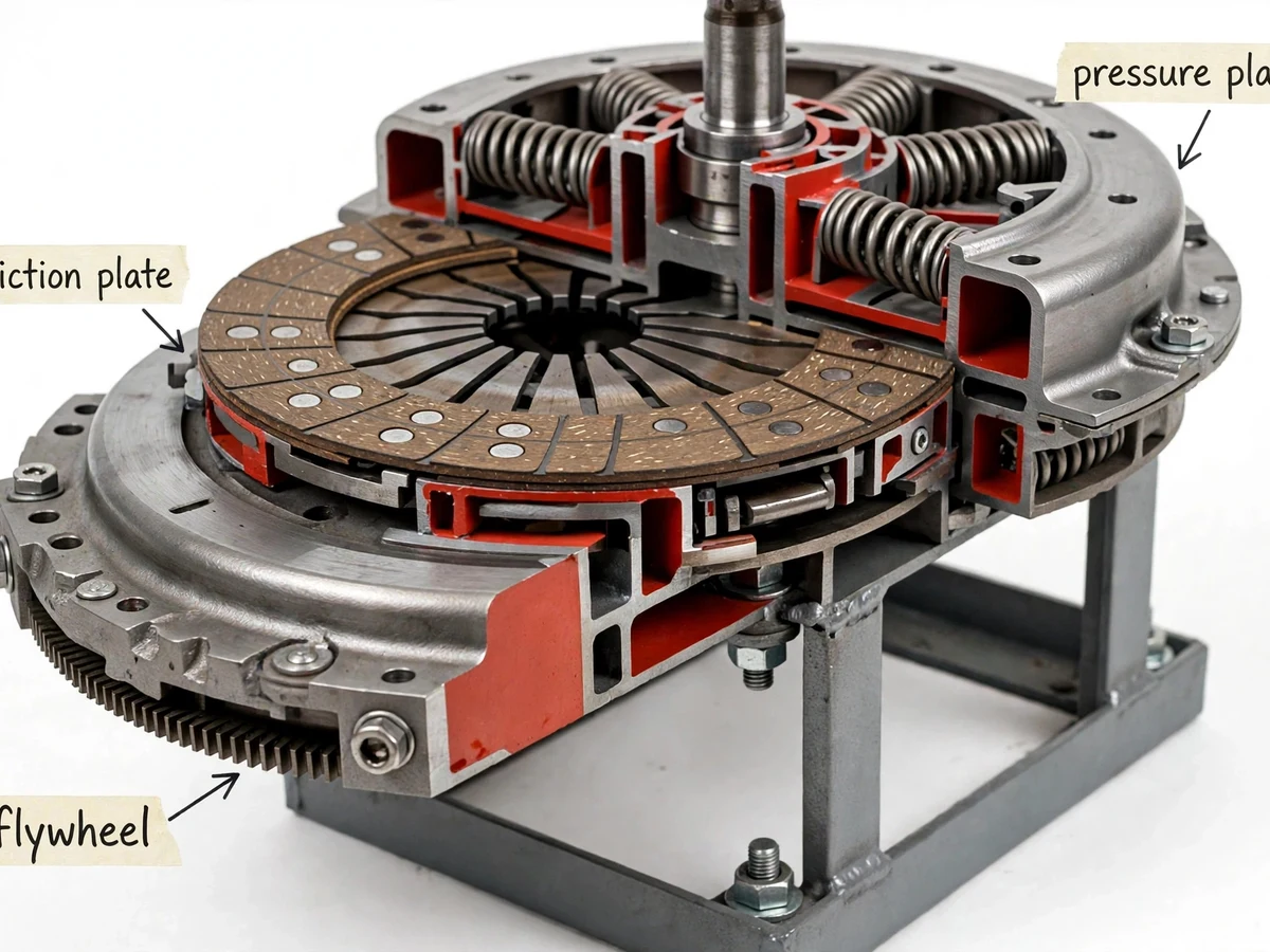
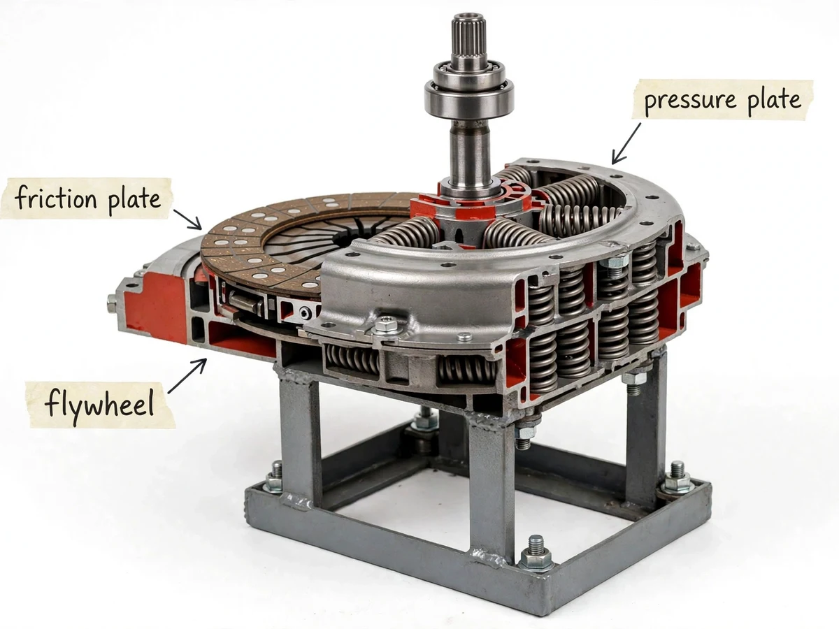
The single plate clutch is the component every mechanical student can name but few have ever seen inside — in a running vehicle it is buried between the engine and gearbox, and in the lab it is usually a poster. A cutaway model solves this by taking a genuine clutch assembly and sectioning it so the friction disc, pressure plate, springs and release bearing are all visible and operable. Mounted on a display stand with labels, the model lets the student pull the release lever and watch the pressure plate lift off the friction disc, then trace exactly how engine torque reaches the gearbox shaft through the splined hub. It is the rare project where the hardware is both the experiment and the exhibit — equally at home in a viva room and a department display case.
How it works
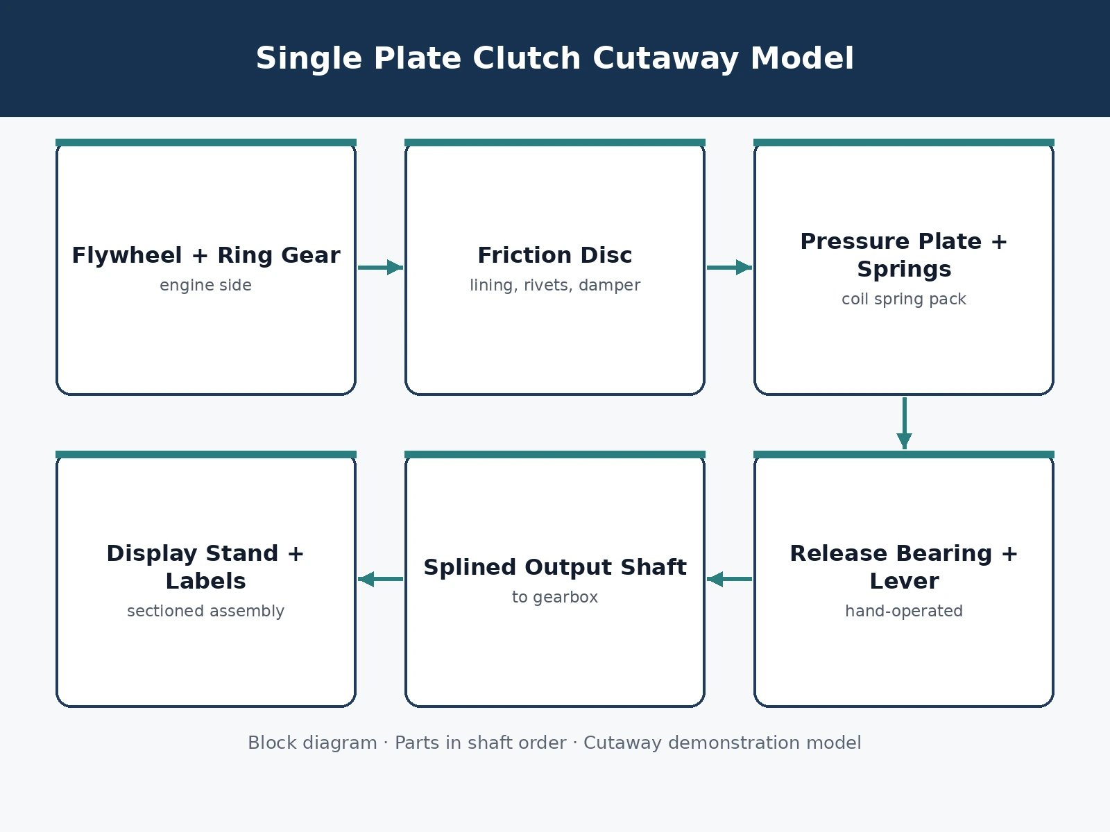
- The student starts at the flywheel: engine torque enters here, and the ring gear and mounting face are identified on the model.
- With the clutch engaged, the pressure-plate springs clamp the friction disc against the flywheel; rotating the flywheel by hand turns the whole assembly together.
- The release lever is pulled: the release bearing pushes the diaphragm/spring fingers, the pressure plate lifts, and the friction disc is freed — the output shaft can now be held still while the flywheel turns.
- Releasing the lever re-engages the pack with a visible snap of the springs, and the power path flywheel → friction disc → splined hub → shaft is traced again.
- Each labelled part is handled in turn — lining wear surface, rivets, damper springs, release bearing — and its function is explained from the hardware.
- The demonstration script is rehearsed until the student can deliver the full engagement-cycle explanation without notes.
Tech stack:
- Genuine single-plate clutch assembly
- Precision sectioning and finishing
- Flywheel with starter ring gear
- Riveted friction disc with damper springs
- Pressure plate and spring pack
- Release bearing and hand lever
- Welded steel display stand
- Guided demonstration script
| Parameter | Value |
|---|---|
| Clutch type | Single dry plate, diaphragm/coil spring (design) |
| Sectioning | Quarter-section cut, cut faces finished and sealed (design) |
| Stand | Welded steel, tabletop height (design) |
| Operation | Manual release lever, hand-rotated (design) |
| Labels | 6 part labels, engraved style (design) |
| Footprint | Approximately 500 × 400 mm (expected) |
| Finish | Cut faces sealed against corrosion (design) |
| Demonstration | Full engagement/disengagement cycle by hand (design) |
Project features
- [Genuine sectioned clutch] A real single-plate clutch assembly, professionally sectioned to expose the friction disc, pressure plate and spring pack while keeping the parts in working relationship.
- [Flywheel with ring gear] The flywheel is retained with its starter ring gear, so the engine side of the power flow is visible and identifiable.
- [Riveted friction disc] The friction disc shows its lining segments, rivets and torsional damper springs — the parts the textbook diagram always labels.
- [Working release lever] A hand lever operates the release bearing and visibly lifts the pressure plate off the disc, demonstrating engagement and disengagement.
- [Splined output shaft] The gearbox-side shaft with its splines engages the disc hub, completing the visible power path from flywheel to output.
- [Welded display stand] A rigid steel stand holds the assembly at viewing height with the cut faces oriented for a group demonstration.
- [Part labels] Engraved-style labels identify the flywheel, friction plate, pressure plate, springs, release bearing and shaft.
- [Demonstration script] A guided talk-through — power flow, engagement sequence, function of each part — the student can deliver in the viva or at an exhibition.
What is included
- Sectioned single plate clutch on welded display stand
- Working release lever and splined output shaft
- Set of 6 engraved-style part labels (fitted)
- Sectioning and stand fabrication drawings
- Guided demonstration script for viva and exhibition
- Project report PDF (background, clutch theory, sectioning method, part functions)
- PPT presentation for final review
- Viva Q&A preparation document (friction drive, spring clamp load, wear, damper springs)
Limitations & prerequisites
- A demonstration and teaching model — it is not a serviceable vehicle clutch and is not rated for engine torque.
- Sectioning removes material, so clamp-load or torque-capacity figures from the donor clutch no longer apply; no performance numbers are claimed.
- The friction lining is the donor part's original surface — wear state varies and is documented as-found in the report.
- Hand operation only; there is no powered spin or automated engagement cycle.
- Cut faces are sealed but the model should be kept dry and dust-covered between demonstrations.
Frequently Asked Questions
Is this a real clutch or a replica?
A real one: a genuine single-plate clutch assembly, sectioned so the internals are visible while the parts stay in their working positions. That is why the release action actually works.
What does pulling the lever show?
The release bearing pressing the spring fingers, the pressure plate lifting off the friction disc, and drive disconnecting — the exact engagement sequence the textbook describes, happening in front of you.
How is the model used in the viva?
The demonstration script walks the examiner through power flow and the engagement cycle on the hardware; most viva questions on clutches can be answered by pointing at the part.
Will the cut edges rust?
The sectioned faces are finished and sealed during preparation; the care sheet covers keeping the model dry and covered between uses.
Can it be displayed at exhibitions?
Yes — the stand, labels and hand operation are designed for exactly that: visitors can work the lever themselves with the script card alongside.
Is this project suitable for a final-year project?
Yes — for Mechanical Engineering programs. It combines automotive component study, precision sectioning work, and demonstration engineering, and the report documents the full teardown-to-exhibit process. Suitable for B.E./B.Tech final-year projects in Mechanical Engineering.
Components & software requirements
- Genuine single-plate clutch assembly
- Precision sectioning and finishing
- Flywheel with starter ring gear
- Riveted friction disc with damper springs
- Pressure plate and spring pack
- Release bearing and hand lever
- Welded steel display stand
- Guided demonstration script
Delivery information
Built-to-order project. Delivery timeline is shared after order confirmation based on current queue.
Support terms
Complete documentation, setup guide, and viva preparation included. Support for setup and explanation provided.
Download free synopsis (PDF)
Enter your name and WhatsApp number — the synopsis PDF downloads immediately. We may send occasional project updates on WhatsApp; no spam.