
More project photos (2)
The problem
Every electricity bill rests on one measurement: energy, the time-integral of power. Utility meters do this with dedicated metrology chips, but the underlying principle — sample v(t) and i(t), multiply, accumulate — is entirely implementable on a microcontroller and makes an excellent teaching build. It forces engagement with the real subtleties: sampling both waveforms simultaneously, why apparent power differs from real power on reactive loads, how calibration constants map ADC counts to volts and amps, and why a meter must remember its accumulated reading through power cuts. This project builds that meter for a single-phase demo circuit: isolated voltage and current sensing, an Arduino integrating real power into kWh, a tariff-based cost display, and a calibration procedure the student performs with a known resistive load — the honest way to claim accuracy.
How it works
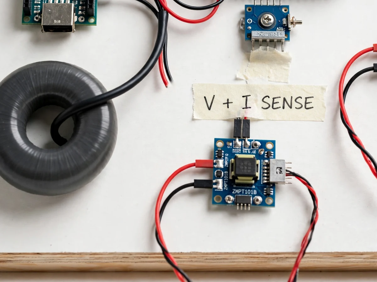
- Isolated voltage sensing (transformer or isolated divider) and a current transformer/Hall sensor feed scaled replicas of the mains waveforms to the Arduino's ADC.
- The firmware samples both channels in quick succession many times per mains cycle, capturing the waveform shapes.
- Each sample pair is multiplied to get instantaneous power; the products are averaged over whole cycles to get real power in watts.
- Real power is integrated over time into watt-hours and accumulated into the kWh register, which is checkpointed to EEPROM.
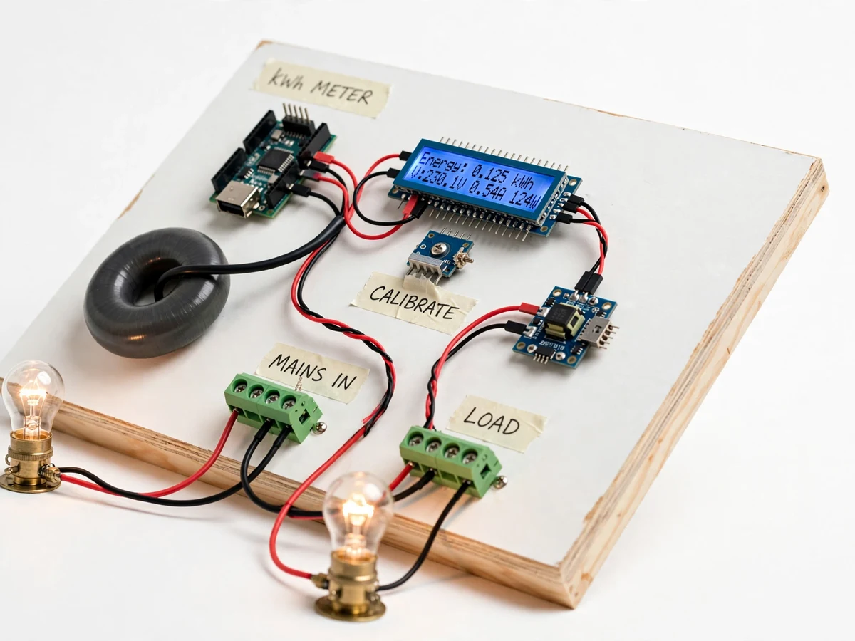
- The LCD shows live V, I, W, estimated PF, accumulated kWh and the cost computed from the configured tariff.
- During setup, the student runs the calibration procedure with a known load, adjusting the voltage and current constants until the meter reads correctly.
- A deliberate long-press resets the register; ordinary button presses only change the display page.
Tech stack:
- Arduino Uno/Nano (ATmega328P)
- Isolated voltage sensing stage
- Current transformer or Hall-effect current sensor
- 16x2 character LCD
- EEPROM (on-chip) for energy backup
- Arduino IDE (C/C++ firmware)
- Single-phase demo load bank (resistive + reactive loads for PF demo)
| Parameter | Value |
|---|---|
| Controller | Arduino Uno/Nano (ATmega328P) |
| Circuit | 230 V AC single-phase demo circuit (design current range matched to sensor; exact range in build notes) |
| Measurement | Simultaneous V and I sampling; real power by sample-wise multiplication; kWh by time integration |
| Display | 16x2 LCD: V, I, W, PF estimate, kWh, cost at configured tariff |
| Backup | kWh register checkpointed to EEPROM; survives power cuts |
| Calibration | Buyer-run procedure against a known resistive load; constants stored in EEPROM |
| Accuracy | Design target in the low single-digit percent after buyer calibration (not pre-measured at build) |
| Output | Serial stream of readings for PC logging/plotting |
Project features
- [True power integration] Voltage and current are sampled together and multiplied sample-by-sample, so the meter registers real power (watts) — correctly lower than V×I on reactive loads — not just apparent power.
- [kWh accumulation with EEPROM backup] Accumulated energy is written to EEPROM periodically and on power-fail detection, so the reading survives outages like a real meter.
- [Tariff-based cost display] A configurable per-unit tariff converts accumulated kWh into a running cost figure on the LCD — the part of metering students actually care about.
- [Buyer-run calibration procedure] Calibration constants are set by the student against a known resistive load (e.g. a rated lamp) following the documented procedure; accuracy is earned, not claimed.
- [Live electrical parameters] The LCD cycles through voltage, current, real power, power factor estimate and accumulated energy, not just the final kWh number.
- [Tamper-evident reset] The energy register resets only through a deliberate long-press sequence, demonstrating why real meters protect their registers.
- [Serial data output] Readings are also streamed over serial for logging and plotting on a PC during the demo.
What is included
- Working digital energy meter prototype (Arduino, isolated V/I sensing, LCD, demo load bank)
- Complete firmware source code (sampling, power integration, EEPROM backup, tariff math, LCD/serial)
- Circuit and wiring documentation with sensor selection notes
- Component list with ratings
- Calibration procedure (buyer-run: calibrate against a known load, verify with reactive load)
- Project report PDF (energy metering theory, sampling, calibration, methodology, test procedure)
- PPT presentation for final review
- Viva Q&A preparation document (real vs apparent power, sampling, calibration, why EEPROM backup)
- Setup and demonstration guide
Limitations & prerequisites
- This is an academic demonstration meter, not a utility-billing instrument; it must not be used for actual billing or installed on building wiring.
- Accuracy is a design target achieved through the buyer's own calibration — the meter ships uncalibrated and final accuracy depends on the sensors and the care taken in calibration.
- Single-phase only; three-phase metering needs three sensing channels, noted as an extension.
- The Arduino ADC resolution and sampling rate limit performance on heavily distorted waveforms; this is documented as a teaching limitation.
- Tariff is a single flat rate in the base build; slab/tiered billing is a possible firmware extension.
Frequently Asked Questions
How does it measure energy?
It samples the voltage and current waveforms together, multiplies each sample pair for instantaneous power, averages over mains cycles for real power, and integrates over time into kWh — the same principle as commercial meters.
Why does it show lower watts than V×I on some loads?
Because it measures real power. On reactive loads (motors, chokes) current and voltage are out of phase, so real power is genuinely less than apparent power — the meter demonstrates this correctly.
How is it calibrated?
With the documented buyer-run procedure: connect a known resistive load (like a rated lamp), and adjust the voltage/current constants until the readings match. Final accuracy comes from your build, not a pre-claimed number.
Does it remember the reading after a power cut?
Yes — the kWh register is checkpointed to EEPROM periodically and on power-fail, so it resumes where it left off.
What are the main limitations?
Demo instrument, not billing-grade; accuracy depends on your calibration; single-phase; flat tariff only in the base build.
Is this project suitable for a final-year project?
Yes — for Electrical programs. Real-vs-apparent power, sampling theory, calibration discipline and non-volatile storage make strong viva material. Suitable for B.E./B.Tech final-year projects in Electrical engineering.
Components & software requirements
- Arduino Uno/Nano (ATmega328P)
- Isolated voltage sensing stage
- Current transformer or Hall-effect current sensor
- 16x2 character LCD
- EEPROM (on-chip) for energy backup
- Arduino IDE (C/C++ firmware)
- Single-phase demo load bank (resistive + reactive loads for PF demo)
Delivery information
Built-to-order project. Delivery timeline is shared after order confirmation based on current queue.
Support terms
Complete documentation, setup guide, and viva preparation included. Support for setup and explanation provided.