
More project photos (2)
The problem
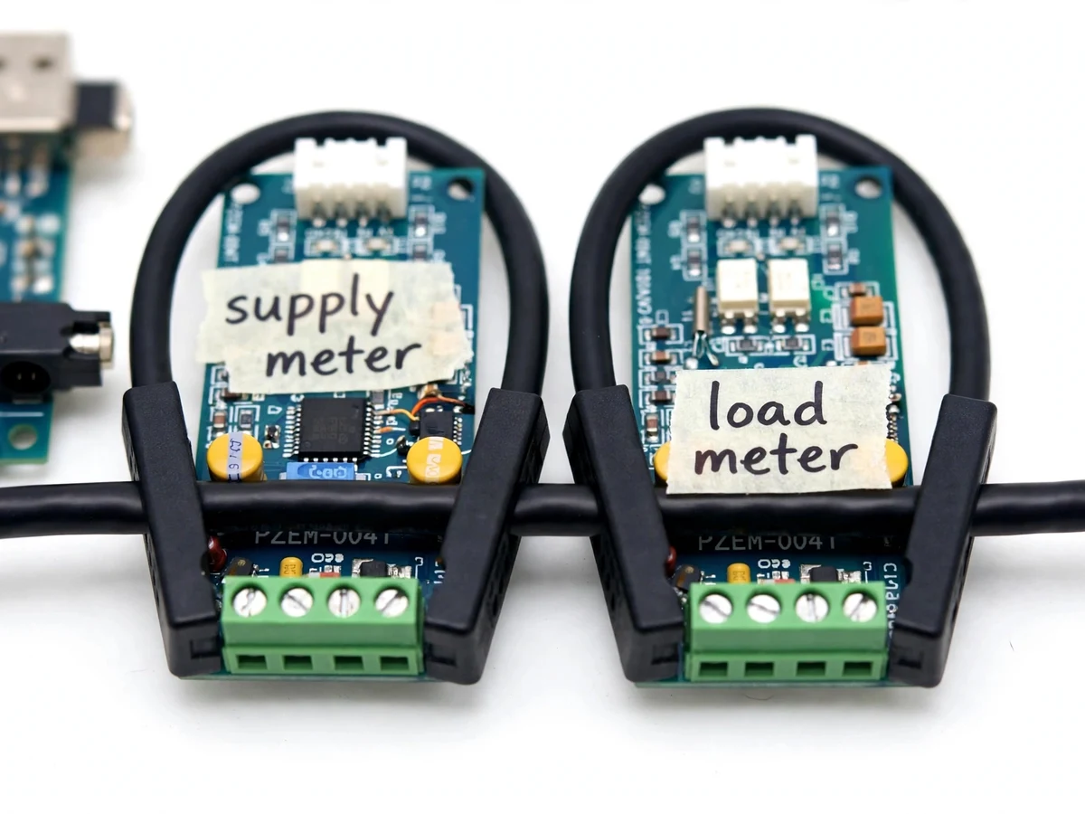
The Single-Phase Energy Theft Detection System catches losses like hooking and bypass in power distribution — by watching the gap between two energy meters rather than either meter alone. One PZEM-004T module with a CT clamp sits at the supply point, a second sits at the consumer load, and an Arduino Uno polls both over serial and compares their energy readings. Under healthy conditions the two readings track within a small tolerance; when energy enters the supply meter but never reaches the load meter, the mismatch crosses a configurable threshold and the system raises theft: a buzzer sounds, and a SIM800L GSM module texts a configured number. Tampering is covered too — if either meter's serial link goes silent, that is flagged as meter interference. The insight is quotable: theft shows up as energy that enters the supply meter but never reaches the load meter — the system watches that gap, not the absolute consumption.
230 V single-phase AC supply feeding the monitored line.
Follow the working sequence
How it works
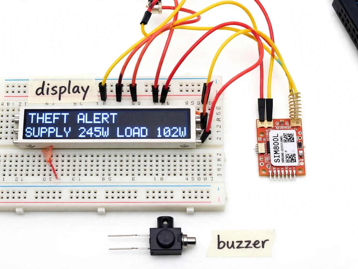
Power enters through the supply CT clamp, travels the monitored line, and exits through the load CT clamp, with each clamp feeding its own PZEM-004T module that measures voltage, current, power and cumulative energy. The Arduino polls the supply meter and the load meter alternately over serial at 9600 bps, keeps a rolling pair of energy readings, and computes the percentage difference between what the supply meter reports and what the load meter reports. A configurable threshold (default 5% as a design target) separates honest losses — small CT tolerances and line drop — from energy drawn between the two points by hooking or bypass. Crossing the threshold raises theft: the LCD switches to the alert screen, the buzzer sounds, and the SIM800L sends an SMS with both readings. Independent of comparison, a watchdog watches both serial links and flags meter-signal loss as tampering.
- A 230 V AC single-phase supply passes through the supply CT clamp, and the monitored cable continues to the consumer load through the load CT clamp.
- Each PZEM-004T module measures voltage (80–260 V AC, datasheet value), current (0–100 A via CT, datasheet value), power and cumulative energy, reporting over serial when polled.
- The Arduino Uno polls both meters alternately at 9600 bps and stores the latest energy pair for comparison.
- Firmware computes the percentage mismatch between the supply reading and the load reading against the configured threshold (default 5%, design target).
- On a mismatch above the threshold, the 16×2 LCD shows the alert screen with both readings, the buzzer sounds, and the SIM800L texts the mismatch to the configured number.
- If either meter stops answering its serial poll, the system flags meter tampering on the LCD and raises a separate alert instead of reporting a theft reading.
- The threshold is a single firmware constant, so sensitivity can be retuned and retested in minutes during the demonstration.
Tech stack:
- Arduino Uno (ATmega328P)
- PZEM-004T energy meter module ×2
- SIM800L GSM module
- 16×2 LCD + piezo buzzer
- Arduino IDE + embedded C
- 100 A CT clamps ×2
- 5 V / 2 A regulated supply
- Git
| Parameter | Value |
|---|---|
| Mains input | 230 V AC single-phase, 50 Hz (typical Indian supply) |
| Voltage measurement range | 80–260 V AC (Datasheet value) |
| Current measurement range | 0–100 A via CT clamp (Datasheet value) |
| Meter communication | 9600 bps TTL serial per meter |
| Theft threshold | 5% mismatch, configurable in firmware (Design target) |
| Alert channels | 16×2 LCD, buzzer, SMS via SIM800L |
| GSM band | Quad-band 850/900/1800/1900 MHz (Datasheet value) |
| Controller | ATmega328P on Arduino Uno, 16 MHz clock |
| SMS requirement | Active SIM with SMS balance; 2G network coverage |
| Power supply | 5 V DC, 2 A regulated (Approximate minimum) |
Project features
Two off-the-shelf AC energy meter modules form the sensing core, each measuring voltage, current, power and energy on a 230 V single-phase line through a 100 A CT clamp, polled alternately by the Arduino over 9600 bps serial. Live comparison logic computes the percentage mismatch between supply and load energy and compares it against a threshold the student can set in firmware (default 5% as a design target), so sensitivity is tuned rather than fixed. Theft response is layered: the 16×2 LCD updates both readings and switches to an alert screen, a buzzer sounds an audible alarm, and the SIM800L sends an SMS naming the mismatch to a configured phone number. Tamper watchdogs treat a silent meter as evidence: if either PZEM-004T stops answering its serial poll, the LCD flags which meter dropped and an alert goes out. The build is honest about what it is — a wired dual-meter comparison system with GSM SMS alerts, not a cloud dashboard.
- [Dual PZEM-004T metering] Two AC energy meter modules measure 80–260 V AC and 0–100 A (datasheet values) via CT clamps — one at the supply point, one at the load.
- [Live mismatch comparison] The Arduino polls both meters over serial and computes the supply-vs-load energy mismatch against a configurable threshold (default 5% design target).
- [16×2 LCD status display] Continuously shows both readings plus system state; switches to an alert screen when the mismatch threshold is crossed.
- [Buzzer alarm] An audible alarm sounds on theft detection or meter-signal loss, useful for on-site demonstration.
- [SIM800L SMS alert] Quad-band GSM module texts the mismatch reading to a configured number — no app, cloud or data plan needed.
- [Tamper detection] Loss of either meter's serial signal is flagged separately from theft, showing which meter went silent.
- [Configurable threshold] Sensitivity is a single firmware constant, so the student can demonstrate the trade-off between false alarms and missed theft during testing.
- [Builder wiring note] The CT clamps must face the load in the same direction on both meters, or the supply reading subtracts instead of adding — the single most common wiring mistake in this build, documented step-by-step in the build guide.
What is included
- Fully assembled and tested dual-meter prototype (Arduino Uno, 2× PZEM-004T with CT clamps, SIM800L, 16×2 LCD, buzzer)
- Arduino firmware source with configurable theft threshold and meter-timeout tamper logic
- Wiring diagram and step-by-step build guide (including the CT-clamp direction note)
- Theft-detection test procedure: healthy run, hooked-load run, disconnected-meter run
- Project report PDF (background, dual-meter principle, methodology, results)
- PPT presentation for final review
- Viva Q&A preparation document (energy measurement, CT principles, GSM AT commands, threshold trade-offs)
Limitations & prerequisites
- This is a demonstration prototype, not utility-grade revenue equipment: it must never be connected to an actual utility service line or billing meter.
- The PZEM-004T's own ±1% (typical) measurement accuracy means the threshold cannot reliably be set below about 3% (Approximate) without false alarms — honest detection starts above instrument noise.
- The SIM800L needs 2G GSM coverage and an active SIM with SMS balance; SMS delivery latency is network-dependent and not guaranteed.
- Mains wiring is involved: assembly and testing must be supervised, with an isolated test supply and proper insulation — the kit includes written mains-safety instructions.
- Detection is comparative only: it cannot identify WHERE the hooking occurs, only that the gap exists between the two meter points.
- GSM alerts are plain SMS — there is no cloud dashboard or app; the project does not claim IoT cloud monitoring.
- Threshold and all stated detection performance are design targets verified by the buyer-run test procedure, not measured laboratory results.
Frequently Asked Questions
How does comparing two meters detect theft?
Theft shows up as energy that enters the supply meter but never reaches the load meter — the system watches that gap, not the absolute consumption. In a healthy circuit both meters agree within a small tolerance; a hooking or bypass between the two meter points makes the supply reading exceed the load reading beyond the configured threshold, which the Arduino flags as theft.
What is the detection threshold and can it be changed?
The default is a 5% mismatch between the two energy readings, set as a design target in a single firmware constant. It can be changed and recompiled in minutes. Because the PZEM-004T has about ±1% (typical) instrument accuracy, setting the threshold much below 3% (Approximate) risks false alarms from measurement noise alone.
Does it need the internet or an app?
No. Alerts go out as plain SMS through the SIM800L quad-band GSM module to a configured phone number, so no app, cloud account or data plan is needed — just an active SIM with SMS balance and 2G coverage. The system is deliberately not an IoT cloud dashboard.
Can it be connected to a real electricity meter?
No — this is a lab prototype for demonstration and viva, built around two low-cost meter modules and test loads. It must never be wired into an actual utility service line or billing meter; mains-safety instructions ship with the kit.
How is tampering handled?
If either PZEM-004T stops answering its serial poll, the Arduino flags meter-signal loss separately from theft, the LCD shows which meter went silent, and an alert is raised. This covers a thief disconnecting or damaging the load-side meter to hide a bypass.
Is this project suitable for a final-year project?
Yes — for Electrical, Electronics and related branches. It demonstrates CT-based energy measurement, serial interfacing of real meter modules, comparison-based fault logic, GSM alerting and honest threshold engineering, all of which make strong viva material and show genuine hands-on electrical work.
Components & software requirements
- Arduino Uno (ATmega328P)
- PZEM-004T energy meter module ×2
- SIM800L GSM module
- 16×2 LCD + piezo buzzer
- Arduino IDE + embedded C
- 100 A CT clamps ×2
- 5 V / 2 A regulated supply
- Git
Delivery information
Built-to-order project. Delivery timeline is shared after order confirmation based on current queue.
Support terms
Complete documentation, setup guide, and viva preparation included. Support for setup and explanation provided.
Download free synopsis (PDF)
Enter your name and WhatsApp number — the synopsis PDF downloads immediately. We may send occasional project updates on WhatsApp; no spam.