
More project photos (2)

The problem
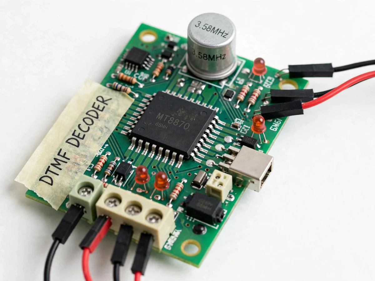
DTMF-based home appliance control solves a problem Wi-Fi smart switches cannot: switching appliances on and off where there is no internet. In farmhouses, village homes and industrial outbuildings, running Wi-Fi to every switch or a cloud app is impractical, yet people still need to run a water pump, a yard light or a fan before they arrive. This project answers a mobile-phone call and toggles four appliances with keypad tones, using the same DTMF signaling every phone network carries. At the receiving end, a SIM800L GSM module auto-answers the call, an MT8870 chip converts each keypress into a digital code, and an Arduino Nano drives a 4-channel relay module. A password key sequence guards access; every action is confirmed by SMS. Any phone that can place a call can operate it — no app, no smartphone, no data plan.
Dials the system number, keys the 4-digit password, then command keys.
Follow the working sequence
How it works
The full chain starts the moment a caller dials the system's SIM number. The SIM800L GSM module auto-answers after the configured number of rings, opening a two-way voice path, and the caller first keys a four-digit password. The call audio — containing the password and command tones — feeds the MT8870 decoder, which splits each dual-tone keypress back into its row and column frequencies, converts them to a 4-bit code and raises its StD data-valid pin when the tone pair passes its internal checks. The Arduino Nano reads the 4-bit nibble only when StD is asserted, verifies the password sequence, then maps keys 1–4 to toggle the four relay channels and key 0 to switch everything off. The relay module's contacts do the actual mains switching while the Nano updates the 16×2 LCD and the SIM800L texts the new state to a configured number, so the caller gets confirmation before hanging up.
- The caller dials the system's SIM number; the SIM800L auto-answers after the configured ring count (ATS0, set to 2 rings in the base firmware as a design target).
- The caller keys the four-digit password; the MT8870 decodes each tone from the call audio into a 4-bit nibble, flagged valid by its StD pin, and the Nano accumulates the sequence.
- If the sequence matches the stored code, the Nano enters command mode and the LCD shows READY; wrong codes are ignored and the call stays locked.
- Keys 1–4 toggle the matching relay channel and key 0 switches all four off; each state is held in the Nano's memory and shown on the LCD.
- After every switch, the SIM800L sends an SMS naming the appliance and its new state to the configured number.
- When the caller hangs up, the relays hold their last state and the system returns to the locked idle state, ready for the next call.
Tech stack:
- SIM800L GSM module
- MT8870 DTMF decoder IC
- Arduino Nano · ATmega328P
- 4-channel 5 V relay module
- 3.579545 MHz crystal
- 16×2 LCD display
- Arduino IDE · embedded C
- 5 V / 2 A regulated supply
| Parameter | Value |
|---|---|
| Decoder | MT8870 with 3.579545 MHz crystal (Datasheet values) |
| DTMF row tones | 697–941 Hz (ITU-T Q.23) |
| DTMF column tones | 1209–1633 Hz (ITU-T Q.23) |
| Decode output | 4-bit BCD + StD data-valid pin |
| Controller | ATmega328P on Arduino Nano, 16 MHz clock |
| Control channels | 4 channels (base build); 8 with optional 8-channel relay module |
| Relay contact rating | 10 A at 250 VAC per channel (Datasheet value, SRD-05VDC) |
| GSM band | Quad-band 850/900/1800/1900 MHz (Datasheet value, SIM800L) |
| Power supply | 5 V DC, 2 A regulated (Approximate minimum) |
| Response | Approximately 1–2 s keypress-to-click (Design target) |
Project features
The four capabilities that define this build are remote control over a plain phone call, password-protected access, true dual-tone decoding and SMS confirmation of every action. Remote control means exactly what it sounds like: the system auto-answers an incoming call on its own SIM, so any phone — basic keypad handset or smartphone, on any network — can operate the four appliances from wherever cellular coverage reaches. Password protection is what makes that safe: until the caller keys the correct four-digit sequence, every tone is ignored, so a wrong number reaching the line cannot switch anything. The MT8870 decoder is the heart of the signal path — it converts each audible keypress into a verified 4-bit code and flags it valid only when both tones pass its digital checks. And after every switch, the SIM800L texts the new status to a configured number, closing the loop.
- [Call-and-control from any phone] The SIM800L auto-answers incoming calls, so any handset on any network can operate the system — no app, no smartphone and no internet on the caller side.
- [MT8870 dual-tone decoding] The MT8870 splits each keypress back into its row and column frequencies, converts it to a 4-bit code and raises its StD data-valid pin only when both tones pass internal digital verification — the firmware latches digits only on StD, so voice-like noise never registers as a command.
- [Password key sequence] The caller must key the correct four-digit code (a firmware constant, default 1234) before any command is accepted; all tones arriving before a correct code are ignored and the line stays locked.
- [Four independent relay channels] Keys 1–4 toggle appliances one to four; key 0 switches everything off at once. The base build carries 4 channels; an 8-channel relay module is available as an optional customization.
- [16×2 LCD status display] Shows call state, the last decoded digit, password status and the on/off state of all four channels — the whole demonstration is visible on the bench.
- [SMS confirmation of every action] After each switch, the SIM800L texts the new appliance state to a configured number, giving the caller proof that the command actually landed.
- [Configurable auto-answer rings] The SIM800L's ATS0 auto-answer setting controls how many rings pass before the system picks up, so the student can tune and demonstrate the trade-off between missed calls and accidental pickups.
- [Builder wiring note] The call audio feeds the MT8870 input through the datasheet's recommended input network documented step-by-step in the build guide, and a 100 nF decoupling capacitor (datasheet application value) sits within ~10 mm of the decoder's supply pin so relay switching noise cannot corrupt tone detection.
What is included
- Fully assembled and tested prototype (Arduino Nano, MT8870 decoder board, SIM800L GSM module, 4-channel relay module, 16×2 LCD)
- Arduino firmware: password verification, StD-validated tone decoding, relay mapping, SMS confirmation, all constants configurable
- Wiring diagram and step-by-step build guide (including the MT8870 input-network and decoupling note)
- Tone-decode test procedure: decoder check with a second phone's keypad tones, then a full call-path test
- Project report PDF (background, DTMF signaling theory, methodology, results)
- PPT presentation for final review
- Viva Q&A preparation document (DTMF theory, MT8870 internals, GSM AT commands, relay driving, the security discussion)
- Written mains-safety instructions for the relay-side wiring and demonstration
Limitations & prerequisites
- Anyone who calls the system's number reaches the controller — the password key sequence is the only barrier. A leaked code means full control, so the code is kept private and changeable as a firmware constant; this limitation is stated openly.
- The SIM800L needs 2G GSM coverage and an active SIM with call and SMS balance; SMS delivery latency is network-dependent and not guaranteed.
- Relay contacts are rated 10 A at 250 VAC (datasheet value) — heavier loads such as large motors or geysers need external contactors, offered as a customization.
- There is no internet dashboard or app: status appears on the LCD and is confirmed by SMS only. The project does not claim IoT cloud monitoring.
- This is a demonstration prototype, not certified switching equipment: relay-side mains wiring must be supervised, properly insulated and enclosed during the build and the demo.
- Tone decoding depends on call audio quality — a badly compressed VoIP leg can distort tones. The StD-validated latching rejects garbage so nothing mis-fires, but a badly degraded call may need a redial.
Frequently Asked Questions
Which decoder and controller does the project use?
The MT8870 DTMF decoder paired with an Arduino Nano (ATmega328P). The MT8870 is a dedicated telephony chip: it splits each keypress into its row and column tones, converts them to a 4-bit code, and raises its StD pin only when the tone pair is digitally verified — the Nano reads the nibble only on StD, so noise never becomes a command. The 3.579545 MHz crystal (datasheet value) is the decoder's clock.
Does it need the internet or a smartphone app?
No — the whole system runs over ordinary 2G voice calls, which is the point of the build: the SIM800L auto-answers the call, the caller presses keys, and confirmation comes back as SMS. Any phone that can place a call can operate it, from a basic keypad handset to a smartphone on any network. The only running cost is an active SIM with call and SMS balance — no data plan, no cloud account, no app.
What stops a stranger who dials the number from switching appliances?
The four-digit password sequence is the only gate, and the firmware is ruthless about it. Until the correct code is keyed, every tone is ignored and the line stays locked — the LCD shows the locked state and no relay moves. The code is a single firmware constant (default 1234), so changing it takes seconds. This limitation is stated openly: the password is the only barrier, so keeping the system's number and code private is part of the design.
Which appliances can it switch, and how many?
Four appliances in the base build: keys 1–4 toggle them individually and key 0 switches everything off at once. Each relay channel is rated 10 A at 250 VAC (datasheet value, SRD-05VDC), so ordinary lights, fans, pumps and chargers are fine. An 8-channel relay module is available as an optional customization, and heavier loads need external contactors.
Can it be customized?
Yes — channel count, passwords and feedback are the easy wins, because the firmware keeps all of them as constants and drives every channel through one relay routine. Realistic options: 8 relay channels, multiple user passwords, a scheduler with an RTC module for timed switching, and custom appliance-name SMS wording. A spoken voice-prompt menu and cloud logging are listed as future scope, not part of the base build.
Is this project suitable for a final-year project?
Yes — for Electronics, E&TC and Electrical programs. The build demonstrates DTMF signaling theory, MT8870 mixed-signal decoding, ATmega328P firmware, GSM AT-command control, relay driving of real mains loads and an honest security discussion about password-only access — strong, hands-on viva material.
Components & software requirements
- SIM800L GSM module
- MT8870 DTMF decoder IC
- Arduino Nano · ATmega328P
- 4-channel 5 V relay module
- 3.579545 MHz crystal
- 16×2 LCD display
- Arduino IDE · embedded C
- 5 V / 2 A regulated supply
Delivery information
Built-to-order project. Delivery timeline is shared after order confirmation based on current queue.
Support terms
Complete documentation, setup guide, and viva preparation included. Support for setup and explanation provided.
Download free synopsis (PDF)
Enter your name and WhatsApp number — the synopsis PDF downloads immediately. We may send occasional project updates on WhatsApp; no spam.