
More project photos (3)
The problem
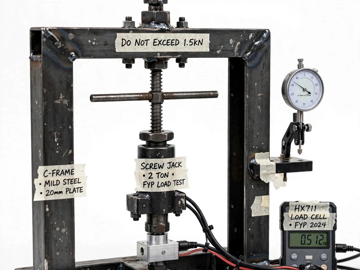
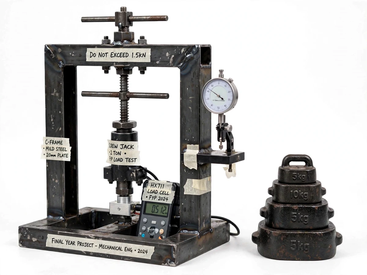
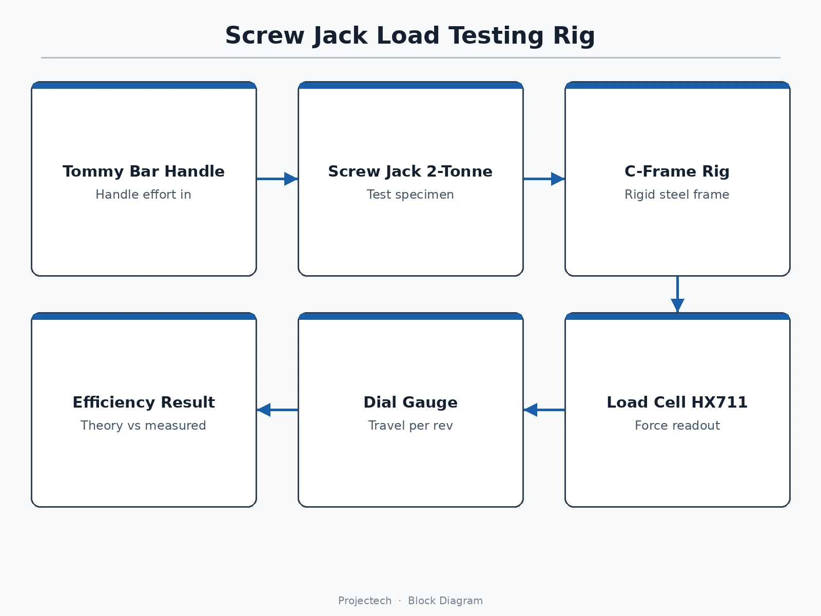
The screw jack is the standard classroom example of power screws, mechanical advantage and efficiency — yet most students never measure a real one. This project builds a dedicated load-testing rig: a 2-tonne screw jack is mounted in a welded mild-steel C-frame, and turning the tommy bar lifts against a load cell that reads the actual axial force while a dial gauge on a magnetic stand measures screw travel per handle revolution. From these two readings the student computes velocity ratio, mechanical advantage and efficiency, and compares them against the theoretical values derived from the screw's pitch and mean diameter. The rig makes friction — the reason real efficiency falls far short of the ideal — visible and quantifiable, which is exactly what makes it a strong viva topic.
Seals the jack in the frame, turns the tommy bar and records load and travel readings.
Follow the working sequence
How it works
- The screw jack is seated in the C-frame and the load cell is zeroed with no load applied.
- A known calibration weight is hung to verify the load-cell reading before testing.
- The tommy bar is turned a counted number of revolutions while the dial gauge records screw travel.
- The load-cell readout gives the axial load corresponding to the measured handle effort.
- Velocity ratio is computed from handle radius versus screw pitch; mechanical advantage from load over effort.
- Efficiency (mechanical advantage divided by velocity ratio) is plotted against load and compared with the theoretical value from the thread geometry.
Tech stack:
- 2-tonne screw jack (test specimen)
- Welded mild-steel C-frame
- HX711 load-cell readout
- Dial gauge with magnetic stand
- Cast-iron calibration weights
- Tommy bar and handle
- Calculation worksheets (report)
- Steel fabrication: cutting, welding, drilling
| Parameter | Value |
|---|---|
| Frame | Mild-steel C-frame, 20 mm plate (design target) |
| Jack capacity | 2-tonne screw jack (nameplate value) |
| Max test load | 1.5 kN, marked on frame (design limit) |
| Load measurement | Load cell + HX711 digital readout (expected resolution per unit datasheet) |
| Travel measurement | Dial gauge, 0.01 mm least count (datasheet value) |
| Calibration weights | 5 kg and 10 kg cast-iron (standard values) |
| Handle | Tommy bar, effort measured via spring scale procedure |
| Overall size | Approximately 500 × 400 × 600 mm (expected) |
Project features
- [Rigid C-frame loading structure] A welded 20 mm mild-steel C-frame holds the screw jack and reacts the full test load with minimal deflection.
- [2-tonne screw jack under test] A standard 2-tonne screw jack with tommy bar is the test specimen, mounted for repeatable axial loading.
- [Load-cell force measurement] An HX711-based load-cell readout displays applied force directly, replacing guesswork with a digital reading.
- [Dial-gauge travel measurement] A dial gauge on a magnetic stand measures screw travel per revolution, giving the second quantity efficiency needs.
- [Calibration weight set] Cast-iron calibration weights (5 kg and 10 kg) allow the load-cell chain to be checked against known masses.
- [Overload guard] The frame carries a marked maximum test load (1.5 kN) and the operating procedure defines safe loading steps.
- [Theory-versus-experiment worksheets] The report includes blank and worked calculation sheets: pitch, mean diameter, helix angle, theoretical versus measured efficiency.
What is included
- Fully fabricated C-frame rig with mounted screw jack
- Load-cell readout unit, zeroed and wired
- Dial gauge with magnetic stand
- Set of calibration weights
- Calibration procedure for the load-cell chain
- Project report PDF (background, power-screw theory, design of frame, experiment procedure, worksheets)
- PPT presentation for final review
- Viva Q&A preparation document (power screws, efficiency, friction angle, self-locking)
Limitations & prerequisites
- Maximum test load is 1.5 kN, well below the jack's 2-tonne rating — the frame is sized for safe laboratory loads, not the jack's full capacity.
- Handle effort is measured with a spring scale in the documented procedure, so effort readings carry the scale's least-count uncertainty.
- Efficiency results are specific to the tested screw's condition; thread wear and lubrication state change the numbers, which the report discusses honestly.
- The rig measures static/quiz-static loading only; it does not test fatigue or impact behaviour.
- Load-cell calibration must be repeated if the unit is transported; the procedure is included.
- The dial gauge must be re-zeroed each session — covered in the experiment steps.
Frequently Asked Questions
What does the rig actually measure?
Two quantities: axial load (via the load cell) and screw travel per handle revolution (via the dial gauge). From these, plus the measured handle effort, you compute velocity ratio, mechanical advantage and efficiency.
Why is measured efficiency lower than theory?
Friction in the threads and collar — the helix-angle analysis in the report shows how friction angle eats into the ideal value, and the experiment quantifies exactly how much.
How is the load cell calibrated?
Known calibration weights (5 kg, 10 kg) are applied and the readout is checked against them; the procedure and a log sheet are included.
Can the rig test other jacks?
Any screw jack of similar size that seats in the C-frame can be tested; the worksheets accept any pitch and diameter values.
What is the maximum safe load?
1.5 kN, marked on the frame. The jack itself is rated 2 tonnes, but the rig's design limit is deliberately lower for laboratory safety.
Is this project suitable for a final-year project?
Yes — for Mechanical Engineering. It is a complete machine-design experiment: fabrication, instrumentation, calibration and theory-versus-experiment analysis. Suitable for B.E./B.Tech final-year projects in Mechanical Engineering.
Components & software requirements
- 2-tonne screw jack (test specimen)
- Welded mild-steel C-frame
- HX711 load-cell readout
- Dial gauge with magnetic stand
- Cast-iron calibration weights
- Tommy bar and handle
- Calculation worksheets (report)
- Steel fabrication: cutting, welding, drilling
Delivery information
Built-to-order project. Delivery timeline is shared after order confirmation based on current queue.
Support terms
Complete documentation, setup guide, and viva preparation included. Support for setup and explanation provided.
Download free synopsis (PDF)
Enter your name and WhatsApp number — the synopsis PDF downloads immediately. We may send occasional project updates on WhatsApp; no spam.