
More project photos (3)
The problem
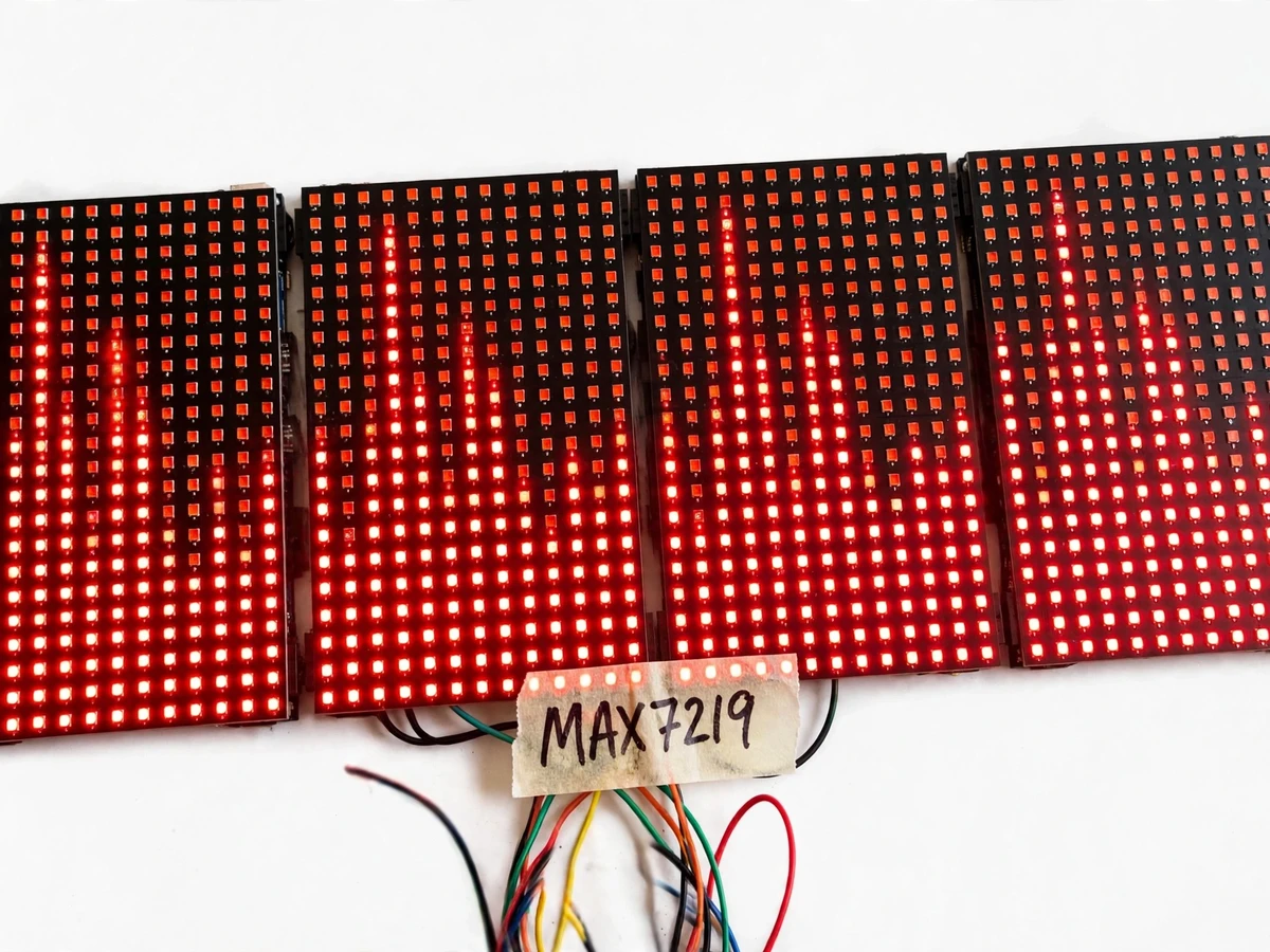
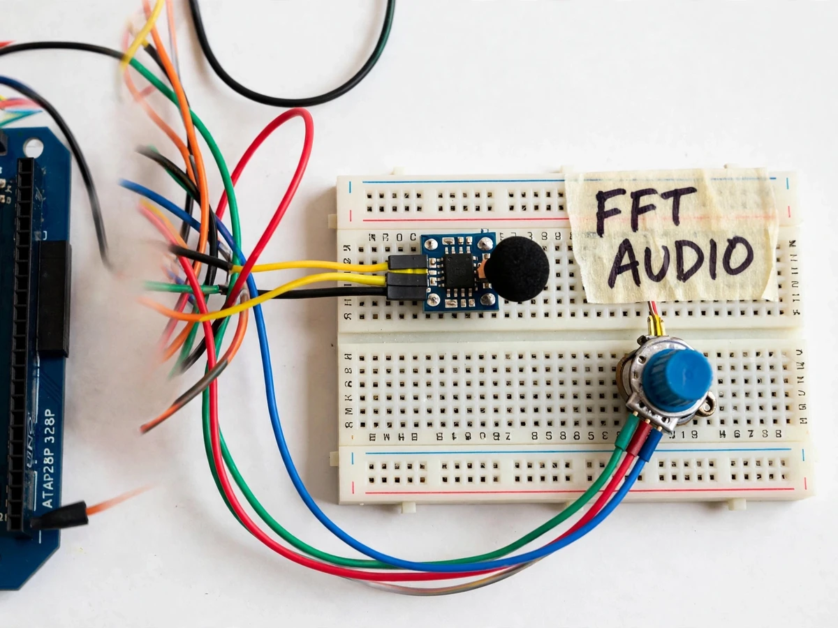
Students learn the Fourier transform as mathematics on a whiteboard and rarely see it operate on a live signal. A real-time spectrum analyzer closes that gap: sound enters a microphone, gets sampled, windowed and transformed, and the frequency content appears instantly as bars on a display. Building one on an Arduino is a genuine embedded-DSP exercise with real constraints — the ADC sample rate, the FFT size that fits in 2 KB of SRAM, and the tradeoff between frequency resolution and update rate are all decisions the student makes and defends. This project implements that chain end to end: an electret mic with a preamp feeds the Arduino ADC, an integer FFT library computes the spectrum, and four chained MAX7219 8x8 modules form a 32x8 matrix showing the bands in real time.
Picks up ambient sound for analysis.
Follow the working sequence
How it works
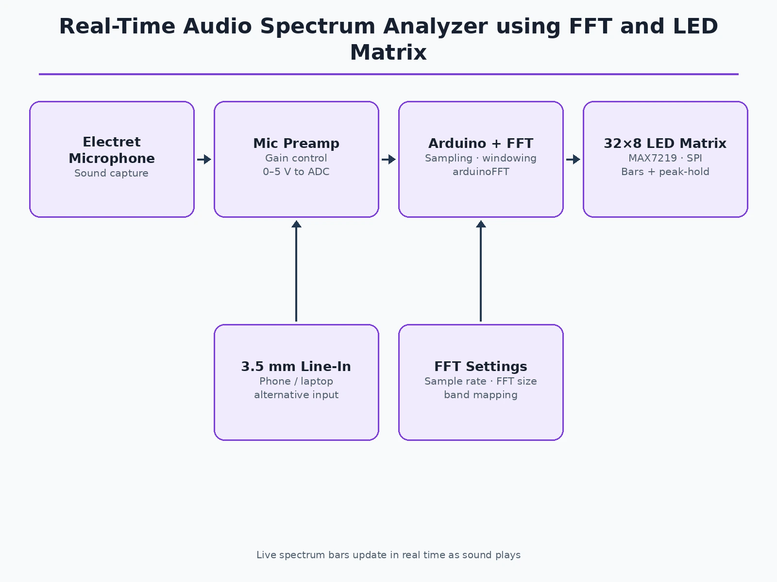
- Sound reaches the electret microphone; the preamp amplifies the millivolt signal to the Arduino's 0–5 V ADC range.
- The Arduino samples the ADC at the configured rate (design target approximately 9.6 kHz) and fills a sample buffer.
- A windowing function is applied to the buffer to reduce spectral leakage at the frame edges.
- The integer FFT library computes the magnitude spectrum from the windowed samples.
- Firmware groups the FFT bins into display bands (logarithmic-ish mapping across the 32 columns) and scales each band to the 8-row height.
- The band heights are shifted out over SPI to the four MAX7219 modules, with peak-hold markers decaying each frame.
Tech stack:
- Arduino Uno (ATmega328P)
- Electret microphone + preamp stage
- 4 × MAX7219 8x8 LED matrix modules (32x8)
- arduinoFFT library (integer FFT)
- 3.5 mm line-in jack, gain potentiometer
- 5 V regulated power supply
- Arduino IDE (C/C++ firmware)
| Parameter | Value |
|---|---|
| Sample rate | Approximately 9.6 kHz (design target, ADC-limited) |
| FFT size | 64 or 128 points, configurable (design) |
| Display | 32 × 8 LEDs via 4 chained MAX7219 modules (design) |
| Frequency span | Approximately 0–4.8 kHz usable (expected, Nyquist-limited) |
| Update rate | Approximately 15–25 frames/sec (expected) |
| Input | Electret mic or 3.5 mm line-in, gain-adjustable (design) |
| Power | 5 V regulated supply, approximately 500 mA max (expected) |
Project features
- [Live FFT spectrum] Audio is sampled and transformed on the Arduino; the 32x8 LED matrix shows the frequency bands updating in real time as music or voice plays.
- [Electret mic with preamp] A biased electret capsule plus a preamp stage conditions the signal to the Arduino's 0–5 V ADC range with a gain control for different sound levels.
- [32x8 MAX7219 matrix display] Four chained 8x8 LED modules form the spectrum display, driven over SPI with per-band bar heights and peak-hold dots.
- [Configurable FFT parameters] Sample rate, FFT size and band mapping are firmware constants, so the student can experiment with resolution-versus-speed tradeoffs.
- [Peak-hold and decay] Each band shows a falling peak marker with configurable decay, giving the display the look and feel of professional analyzers.
- [Line-in option] A 3.5 mm jack input lets the analyzer run from a phone or laptop output as an alternative to the microphone.
- [Gain calibration] A potentiometer sets input gain; the report includes a procedure for setting it without clipping the ADC.
What is included
- Electret microphone preamp module with gain control
- 32x8 LED matrix display (4 × MAX7219 modules)
- Arduino Uno with spectrum-analyzer firmware
- Line-in cable and 5 V power supply
- Wiring diagrams and assembly guide
- Project report PDF (sampling, FFT, display driving, calibration)
- PPT presentation for final review
- Viva Q&A preparation document
Limitations & prerequisites
- The Arduino's ADC and SRAM cap the design: 128-point FFT at ~9.6 kHz is the practical ceiling, so this is a teaching analyzer, not lab-grade instrumentation.
- Usable span is roughly 0–4.8 kHz (Nyquist); bass and treble detail beyond that is out of scope for this hardware.
- The electret mic picks up room noise; the report documents gain setting and placement for clean demos.
- Band mapping is approximate — adjacent bands share FFT bins, so it shows energy distribution, not precise per-Hertz measurement.
- LED brightness at full white can exceed USB current limits; the build uses a dedicated 5 V supply as specified.
Frequently Asked Questions
What does the FFT actually do here?
It converts each block of time-domain audio samples into frequency-domain magnitudes — the firmware then maps those magnitudes to the 32 bar columns you see dancing on the matrix.
Why only up to about 4.8 kHz?
The Arduino samples at roughly 9.6 kHz, and the Nyquist rule says only frequencies below half the sample rate can be represented — a real, defensible hardware limit.
Can I change the number of bands or sensitivity?
Yes — FFT size, sample rate, band mapping and gain are all firmware constants, and the report explains the tradeoff each one controls.
Does it work with music from my phone?
Yes — besides the microphone there is a 3.5 mm line-in jack, so you can feed it directly from a phone or laptop.
Is this project suitable for a final-year project?
Yes — for Electronics, E&TC and Instrumentation programs. It demonstrates sampling, the FFT, spectral display driving and real embedded constraints in one visible build. Suitable for B.E./B.Tech final-year projects in Electronics, E&TC and Instrumentation.
Components & software requirements
- Arduino Uno (ATmega328P)
- Electret microphone + preamp stage
- 4 × MAX7219 8x8 LED matrix modules (32x8)
- arduinoFFT library (integer FFT)
- 3.5 mm line-in jack, gain potentiometer
- 5 V regulated power supply
- Arduino IDE (C/C++ firmware)
Delivery information
Built-to-order project. Delivery timeline is shared after order confirmation based on current queue.
Support terms
Complete documentation, setup guide, and viva preparation included. Support for setup and explanation provided.
Download free synopsis (PDF)
Enter your name and WhatsApp number — the synopsis PDF downloads immediately. We may send occasional project updates on WhatsApp; no spam.