
More project photos (2)
The problem
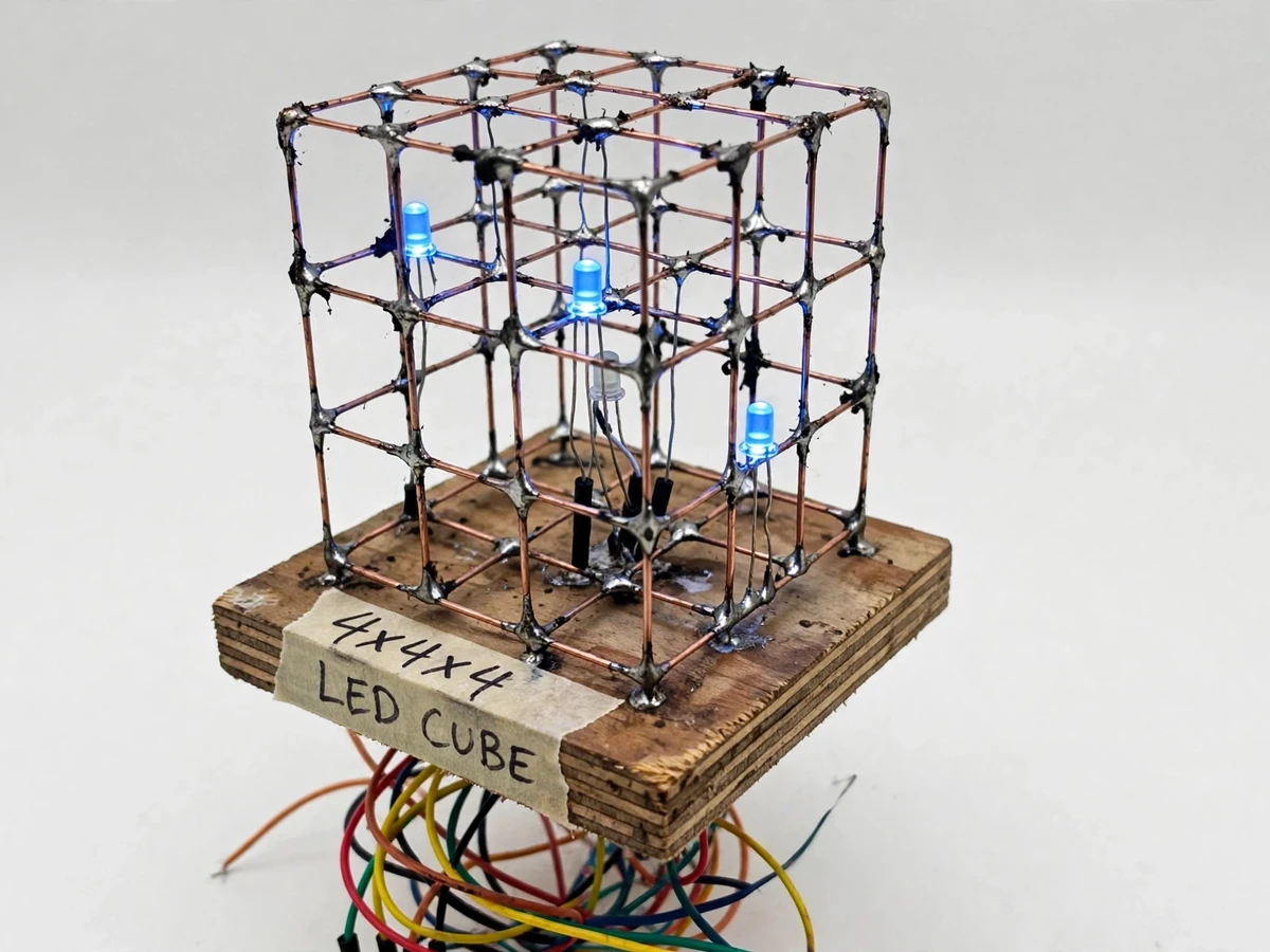
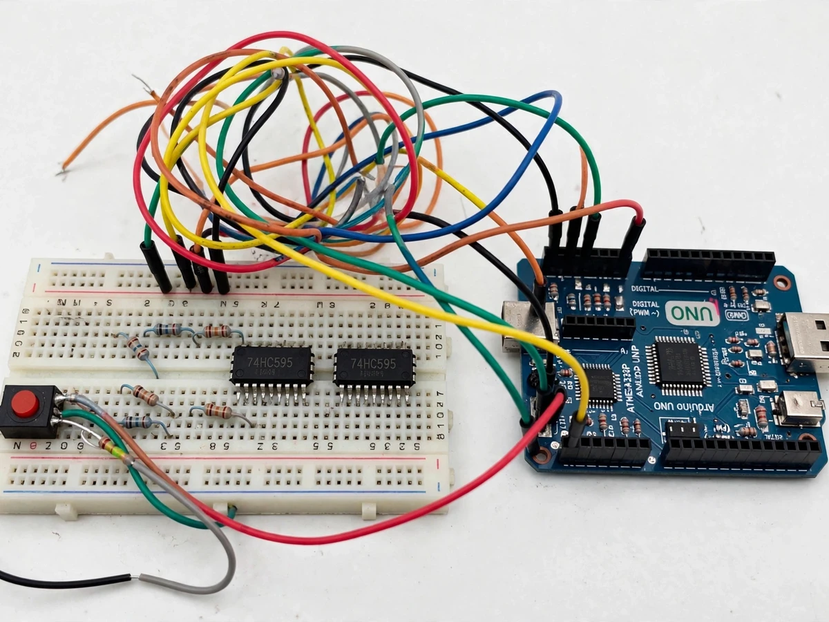
An LED cube is the rite-of-passage electronics build for a reason: it forces the student to do everything at once — solder 64 LEDs into a mechanically sound 3D frame, drive them with far fewer microcontroller pins than LEDs through multiplexing and shift registers, and write animation code in three dimensions. The engineering core is layered multiplexing: only one of the four layers is powered at a time, cycling fast enough that persistence of vision shows a complete 3D image, while two 74HC595 shift registers select which of the 16 columns in the active layer light up. This project delivers that full build — a hand-soldered 4x4x4 cube on a wooden base, transistor-driven layers, shift-register column drivers, and a firmware library of 3D patterns from rain and plane-sweeps to expanding spheres.
How it works
- The 64 LEDs are soldered as 4 layers of 4x4 grids; all anodes in a vertical column are joined, and all cathodes in a layer are joined.
- Two cascaded 74HC595 shift registers drive the 16 column lines through current-limiting resistors.
- Four NPN transistors (or a ULN2803) sink the layer cathodes, enabling one layer at a time.
- Firmware shifts out the 16-bit column pattern for the active layer, enables that layer's transistor for a short slice, then moves to the next layer.
- Cycling all four layers faster than the eye can follow renders a stable 3D image by persistence of vision.
- The animation engine updates a 4x4x4 frame buffer in 3D coordinates and pushes it to the multiplexing routine each frame.
Tech stack:
- Arduino Uno (ATmega328P)
- 64 × 5 mm LEDs (single colour)
- 2 × 74HC595 shift registers (cascaded)
- NPN transistors / ULN2803 for layer drive
- Wooden base, resistors, push button, speed potentiometer
- 5 V regulated power supply
- Arduino IDE (C/C++ firmware)
| Parameter | Value |
|---|---|
| Cube size | 4 × 4 × 4 = 64 LEDs (design) |
| Column drive | 2 × cascaded 74HC595 via SPI/bit-bang (design) |
| Layer drive | 4 × transistor-switched layers (design) |
| Multiplex rate | Design target approximately 60+ full-frame refreshes/sec (expected) |
| LED current | Approximately 20 mA per LED via series resistors (design target) |
| Patterns | 8+ coded 3D animations (design) |
| Power | 5 V regulated, approximately 600 mA max (expected) |
Project features
- [Hand-soldered 4x4x4 grid] 64 LEDs soldered into a rigid 3D frame on a wooden base — the craftsmanship of the build is part of the deliverable.
- [74HC595 shift-register drive] Two cascaded shift registers select the 16 columns using only 3 Arduino pins, demonstrating serial-to-parallel expansion.
- [Layered multiplexing] Four transistor-driven layers switch in rapid sequence; persistence of vision renders the full 3D image from one active layer at a time.
- [3D animation library] Firmware includes coded patterns — rain, plane sweeps, expanding/contracting cube, random sparkles — each written as 3D frame logic.
- [Pattern speed control] A potentiometer adjusts animation speed live, and a push button cycles through the pattern set.
- [Current-limited design] Series resistors and transistor layer drivers keep every LED within its rated current; the design targets standard 20 mA operation.
- [Extensible frame code] The animation engine exposes a simple set-voxel API so the student can code and demonstrate their own pattern.
What is included
- Hand-soldered 4x4x4 LED cube on wooden base
- Driver electronics (shift registers, layer transistors, controls)
- Arduino with animation firmware and pattern library
- 5 V power supply
- Soldering/assembly guide and wiring diagrams
- Project report PDF (multiplexing, shift registers, POV, pattern math)
- PPT presentation for final review
- Viva Q&A preparation document
Limitations & prerequisites
- Single-colour LEDs only — RGB would need three times the drivers and is listed as future scope.
- 4x4x4 is the practical hand-soldered size; an 8x8x8 cube needs 512 LEDs and a different driver architecture.
- Brightness is multiplexed (each LED is on 1/4 of the time), so the cube suits indoor demo lighting, not daylight visibility.
- Soldering quality determines mechanical strength; the assembly guide documents the jig technique used.
- The pattern set is coded in firmware — adding new patterns needs a code change and re-upload, documented in the guide.
Frequently Asked Questions
How can 64 LEDs run from so few Arduino pins?
Two tricks: shift registers expand 3 pins into 16 column lines, and layered multiplexing lights one 16-LED layer at a time, cycling so fast the eye sees all four.
Why does the whole cube appear lit if only one layer is on?
Persistence of vision — the layers cycle at 60+ full frames per second, faster than the eye can resolve, so the brain merges them into a steady 3D image.
Can I add my own animation?
Yes — the firmware exposes a set-voxel(x, y, z) function; the guide shows how to code a new pattern and add it to the cycle button.
Is the cube fragile?
The LEDs are soldered into a rigid wire frame on a wooden base; handled normally it survives transport and demo handling, and the guide covers safe packing.
Is this project suitable for a final-year project?
Yes — for Electronics and E&TC programs. It demonstrates soldering craftsmanship, multiplexing, shift registers, persistence of vision and 3D firmware logic. Suitable for B.E./B.Tech final-year projects in Electronics and E&TC.
Components & software requirements
- Arduino Uno (ATmega328P)
- 64 × 5 mm LEDs (single colour)
- 2 × 74HC595 shift registers (cascaded)
- NPN transistors / ULN2803 for layer drive
- Wooden base, resistors, push button, speed potentiometer
- 5 V regulated power supply
- Arduino IDE (C/C++ firmware)
Delivery information
Built-to-order project. Delivery timeline is shared after order confirmation based on current queue.
Support terms
Complete documentation, setup guide, and viva preparation included. Support for setup and explanation provided.