
More project photos (3)
The problem
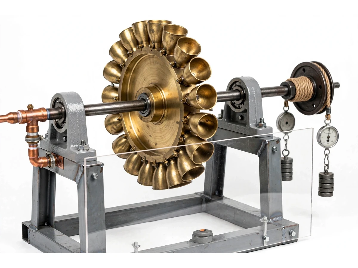
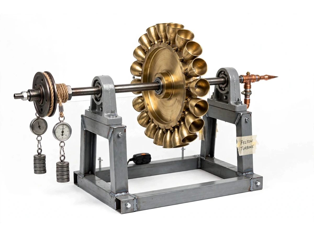
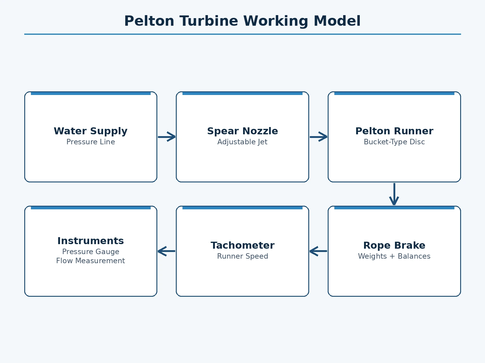
The Pelton turbine is the textbook impulse turbine, yet in most fluid-mechanics courses it stays a diagram: students memorize that the optimum bucket speed is about half the jet velocity without ever watching an efficiency curve rise and fall. This project fabricates a working bench-scale Pelton model — a bucket runner on a shaft, a spear-type nozzle fed from an overhead tank or pump line, a rope brake for applying load, a tachometer, and pressure gauges on the supply. The student runs the classic turbine test: at a fixed head, the brake load is varied in steps, speed and brake torque are recorded at each step, and shaft power, water power and efficiency are computed from the student's own readings. Plotting efficiency against the speed ratio (bucket speed ÷ jet velocity) reproduces the theory curve from measured data, and the peak location confirms — or honestly challenges — the 0.5 textbook figure on the student's own build.
Sets the test head, applies brake load in steps, and records RPM and balances.
Follow the working sequence
How it works
- Set the overhead tank level (or pump supply) to establish the test head, and open the spear nozzle to the chosen jet setting.
- With the rope brake slack, record the runaway (no-load) speed with the tachometer.
- Apply brake load in steps with the hanging weights; at each step wait for steady speed, then record tachometer RPM, the two spring-balance readings, supply pressure and flow.
- Compute brake torque from the balance difference times the brake-drum radius, and shaft power as 2πNT/60.
- Compute jet velocity from the measured head (Torricelli check) or measured flow ÷ nozzle area, and water power as ρ·g·Q·H.
- Compute efficiency at each load step and the speed ratio u/v, where u is bucket tangential speed from RPM and runner diameter.
- Plot efficiency vs speed ratio from your own data and locate the peak — the experiment's verdict on the textbook 0.5 optimum.
Tech stack:
- Fabricated bucket-type Pelton runner
- Spear-type nozzle with jet control
- Overhead tank / pump-fed supply line
- Rope brake with weights and spring balances
- Non-contact tachometer
- Pressure gauge + flow measurement
- Plummer-block bearings on MS frame
- Acrylic splash guard
| Parameter | Value |
|---|---|
| Runner diameter | Approximately 150 mm (design target) |
| Test head | Approximately 3–5 m from overhead supply (design target) |
| Nozzle | Spear-type, adjustable jet (design target) |
| Speed range | Approximately 300–1200 RPM (expected) |
| Loading | Rope brake with spring balances (student-measured torque) |
| Frame size | Approximately 700 × 450 × 900 mm |
| Guard | Transparent acrylic splash enclosure |
| Supply | Water head from tank or pump; 230 V for supply pump if used |
Project features
- [Bucket-type Pelton runner] Machined bucket set mounted on a steel runner disc with a shaft and bearings — the heart of the model, visibly deflecting the jet through nearly 180°.
- [Spear-type nozzle with control] An adjustable spear varies the jet diameter, so the student can test at different flow settings and observe the effect on power.
- [Rope brake loading] A rope-and-pulley brake with hanging weights and spring balances applies a measurable torque — the standard, transparent way to load small turbine test rigs.
- [Head and flow instrumentation] A pressure gauge on the supply line and a flow measurement arrangement (rotameter or timed tank) give the water power input from measured values.
- [Non-contact tachometer] Runner speed is recorded at every load step, so the speed ratio u/v is computed point by point.
- [Transparent splash guard] An acrylic guard keeps the test area dry while leaving the jet-and-bucket action fully visible for demonstration.
- [Welded steel frame and bearing pedestals] Rigid plummer-block mounting keeps the shaft aligned across the full speed range.
- [Theory curve from your data] Efficiency-vs-speed-ratio is plotted from the student's own readings; the report guides the comparison with impulse-turbine theory.
What is included
- Fabricated Pelton turbine model: runner, shaft, bearings, frame
- Spear nozzle and supply piping with pressure gauge
- Rope brake assembly with weights and spring balances
- Non-contact tachometer
- Acrylic splash guard
- Step-by-step test procedure manual
- Observation and calculation sheets (blank, for your readings)
- Project report PDF (impulse-turbine theory, procedure, sample calculations)
- PPT presentation for final review
- Viva Q&A preparation document
Limitations & prerequisites
- This is a demonstration-scale model; its absolute efficiency is student-measured and not claimed — small rigs lose more to friction and splash than full-size turbines.
- The 0.5 speed-ratio optimum is the theoretical figure; the measured peak on a student build typically lands near it but is reported as measured, not assumed.
- Head must stay approximately constant during a test run; a falling tank level shifts every point on the curve.
- Rope-brake readings need steady speed — rushing the steps produces scattered points.
- The rig is for clean water only; grit in the supply scores the buckets and nozzle.
Frequently Asked Questions
What does the student actually measure?
At each brake-load step: runner RPM, the two spring-balance readings (for torque), supply pressure (for head) and flow. From these the student computes shaft power, water power, efficiency and the speed ratio — every plotted point is their own data.
Why a rope brake instead of a generator?
A rope brake makes torque directly measurable with spring balances and hanging weights — transparent, cheap and exactly how small turbine rigs are loaded in teaching labs. A generator load is listed as future scope.
How is the jet velocity found?
Two ways, and the student can compare them: from the measured head using Torricelli's relation, or from measured flow divided by the nozzle area. The manual works through both.
Can the student test at different heads?
Yes — the overhead tank level or the supply valve sets the head, so the full test can be repeated at two or three heads to show how power scales with head.
What impulse-turbine theory does the viva cover?
Jet deflection through the buckets, why the 165–180° deflection matters, the derivation of the 0.5 optimum speed ratio, runaway speed, and governing — all tied to the student's own efficiency curve.
Is this project suitable for a final-year project?
Yes — for Mechanical Engineering. It is the classic fluid-machinery laboratory experiment, built as a visible working model with a theory-verifying test the student performs themselves. Suitable for B.E./B.Tech final-year projects in Mechanical Engineering.
Components & software requirements
- Fabricated bucket-type Pelton runner
- Spear-type nozzle with jet control
- Overhead tank / pump-fed supply line
- Rope brake with weights and spring balances
- Non-contact tachometer
- Pressure gauge + flow measurement
- Plummer-block bearings on MS frame
- Acrylic splash guard
Delivery information
Built-to-order project. Delivery timeline is shared after order confirmation based on current queue.
Support terms
Complete documentation, setup guide, and viva preparation included. Support for setup and explanation provided.
Download free synopsis (PDF)
Enter your name and WhatsApp number — the synopsis PDF downloads immediately. We may send occasional project updates on WhatsApp; no spam.