
More project photos (2)

The problem
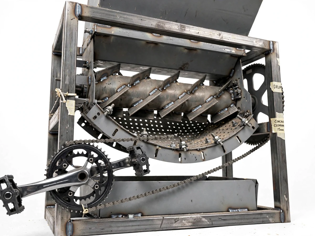
Small farms and teaching farms still thresh grain the slow way: beating crop bundles against a hard surface — slow, tiring and wasteful. The pedal-powered grain thresher with adjustable concave clearance needs no electricity or fuel. The operator pedals a bicycle crank; a roller chain steps the speed up roughly 3:1 and spins the threshing drum — a steel cylinder fitted with angled rasp bars — over a curved, perforated steel concave. Threshing works as agricultural-engineering texts describe it: the rotating rasp bars beat the crop against the stationary concave, and the combined impact and rubbing strip grain from straw while the concave holds the straw inside and lets grain and chaff fall through to the collection tray. The drum-to-concave clearance is the heart of the design: published practice keeps it near 15–25 mm for wheat and 20–30 mm for paddy, and here it is set by sliding the concave on slotted mounting holes and checking with a feeler gauge before bolting.
Pedals the bicycle crank at about 60 rpm.
Follow the working sequence
How it works
The pedal-powered grain thresher converts leg power into threshing work in one chain of motion: the operator pedals a bicycle crank; a roller chain carries that rotation to the drum sprocket with roughly a 3:1 step-up, spinning the rasp-bar drum near 180 rpm; crop bundles fed through the sheet-metal hopper drop into the threshing chamber, where the rotating rasp bars beat the crop against the stationary perforated concave; impact and rubbing strip the grain from the straw; the concave holds the straw inside while grain and small chaff fall through the holes into the collection tray; spent straw is pushed axially by the angled rasp bars to the straw outlet. The concave clearance — the gap between rasp-bar tips and concave — is set before the run by sliding the concave in its slotted mounts and checking with a feeler gauge: a tighter gap threshes more aggressively, a wider gap is gentler on the grain.
- The operator pedals the bicycle crank at a comfortable cadence (design assumption: ~60 rpm); the crankset is mounted on its own brackets on the main frame.
- A bicycle roller chain transmits the crank motion to the drum shaft sprocket with a step-up of about 3.1:1 (44T chainring, 14T sprocket — design parameter).
- The rasp-bar drum spins at roughly 180 rpm (design target), carried on two plummer-block bearings; a chain guard covers the drive for safety.
- Dried crop bundles are fed by hand through the feed hopper into the threshing chamber — the hopper keeps hands clear of the rotating drum.
- The rotating rasp bars beat the crop against the stationary perforated concave; impact plus rubbing separate grain from straw, exactly the principle of conventional drum threshers.
- Grain and small chaff fall through the concave perforations into the removable collection tray; straw is carried axially by the angled bars to the straw outlet.
- After the run, grain from the tray is winnowed to remove chaff; concave clearance is re-set with the feeler gauge if a different crop (wheat vs paddy) is threshed next.
Tech stack:
- MS square-tube frame · SMAW welding
- Bicycle crankset & pedal drive
- Roller-chain transmission (~3:1)
- Rasp-bar threshing drum
- Perforated-sheet concave · slotted mounts
- Plummer-block bearings
- Feeler-gauge clearance setting
- Design calculation set (chain · shaft · frame)
| Parameter | Value |
|---|---|
| Overall size | Approximately 1100 × 700 × 1200 mm (design target) |
| Threshing drum | Steel cylinder, ~200 mm diameter × 600 mm long, 6 rasp bars (design target) |
| Chain drive | 44T chainring → 14T sprocket, step-up ~3.1:1 (design parameter) |
| Drum speed | Approximately 180 rpm at 60 rpm pedaling cadence (design target) |
| Concave clearance | 10–30 mm adjustable via slotted mounts, set with feeler gauge (design parameter) |
| Published clearance practice | 15–25 mm for wheat, 20–30 mm for paddy (reference, agri-engineering texts) |
| Chain | Bicycle roller chain, 1/2" pitch (design parameter) |
| Bearings | 2 × plummer-block units on drum shaft (design parameter) |
| Throughput | 30–50 kg/h (design target; depends on crop, feed rate and operator) |
| Frame | Welded MS square tube with anti-vibration mounts (design parameter) |
Project features
A pedal-powered grain thresher with adjustable concave clearance brings together three things a final-year build should show: a real agricultural process, a working power-transmission design, and an adjustment that is genuinely measurable. The core capability is human-powered threshing with no electricity — a bicycle crank and roller chain deliver roughly a 3:1 step-up, so a comfortable 60 rpm cadence spins the drum near 180 rpm. The second is the adjustable concave: the curved perforated sheet rides in slotted mounting holes, so the drum-to-concave gap can be set between 10 and 30 mm with a feeler gauge, matching published practice of 15–25 mm for wheat and 20–30 mm for paddy. The third is crop adaptability — the feed hopper, the drum rasp-bar angle and the clearance setting let the same machine handle wheat and paddy without redesign. The fourth is buildable construction: standard square-tube steel, a bicycle chainset and plummer-block bearings keep every part replaceable in a college workshop.
- [Bicycle pedal crank drive] A standard bicycle crankset and pedals feed a roller chain to the drum sprocket; pedaling at a comfortable cadence (design assumption: ~60 rpm) drives the threshing drum with no motor, battery or fuel.
- [Approximately 3:1 chain step-up] A 44-tooth chainring driving a 14-tooth sprocket steps drum speed up about 3.1× over pedaling cadence, giving a drum speed near 180 rpm at 60 rpm pedaling (design target).
- [Rasp-bar threshing drum] A steel cylinder fitted with angled rasp bars beats crop against the concave by impact and rubbing — the same separation principle used in conventional power threshers — while the bar angle also feeds straw axially toward the outlet.
- [Adjustable concave clearance] The perforated concave mounts on slotted holes with bolts: loosen, slide to the required gap, verify with a feeler gauge at the inlet, middle and rear, then lock. Range 10–30 mm (design parameter); published practice is 15–25 mm for wheat and 20–30 mm for paddy.
- [Feed hopper + straw outlet] A sheet-metal hopper guides crop into the threshing chamber safely away from the drum, and spent straw exits through a separate outlet — no hands go near the rotating drum.
- [Grain collection tray] Threshed grain and small chaff fall through the concave perforations into a removable tray under the chamber, so output is ready for weighing and winnowing.
- [Bolted plummer-block bearings] The drum shaft runs in two plummer-block bearing units, a real-world bearing-selection exercise with documented load and mounting geometry.
- [Workshop-fabricated frame] A welded square-tube mild-steel frame with anti-vibration mounting carries the drum, crankset and bearings — fabricated with standard SMAW welding and hand tools.
What is included
- Working pedal-powered grain thresher prototype (pedal crank, chain drive, rasp-bar drum, adjustable concave, hopper, collection tray)
- Fabrication drawings: frame, drum assembly, concave with slotted mounts, hopper
- Design-calculation report: chain-drive ratio and chain selection, shaft sizing, bearing selection, frame loading
- Adjustment and operation manual: feeler-gauge clearance procedure, crop settings (wheat/paddy), feeding and safety procedure
- Project abstract PDF (10-section, matches this page)
- Project report (background, threshing theory, methodology, calculations)
- PPT presentation for final review
- Viva Q&A preparation document (threshing principle, chain drive, concave clearance, maintenance)
Limitations & prerequisites
- Crop-specific settings are required: wheat and paddy need different concave clearances (15–25 mm vs 20–30 mm per published practice); one setting does not suit both.
- Excessive drum speed — pedaling far beyond the design cadence — raises grain damage and cracking risk; the operator must hold a steady rhythm.
- Crop is fed by hand through the hopper only; hands must never reach into the threshing chamber while the drum turns. A chain guard covers the drive.
- Throughput of 30–50 kg/h is a design target, not a measured figure; actual output depends on crop condition, feed rate and operator stamina.
- Pedaling is tiring over long runs; continuous operation needs operator rotation (roughly every 20–30 min per operator, guideline only).
- The concave perforation size suits small grains (wheat, paddy); maize-scale ears need a different concave sheet — listed as a customization.
- This is an academic prototype, not a certified agricultural machine; no claim is made about field durability or commercial throughput.
- Threshing creates dust and noise; outdoor or ventilated-area demonstration is recommended.
Frequently Asked Questions
What is the main mechanical principle of this project?
The project separates grain by impact and rubbing between a rotating rasp-bar drum and a stationary perforated concave — the standard threshing principle described in agricultural-engineering references. Leg power from a bicycle crank drives the drum through a roller-chain step-up, and the concave holds straw in the chamber while grain falls through its perforations.
How is the concave clearance actually set?
By a builder procedure: loosen the concave mounting bolts, slide the concave in its elongated slotted holes, insert a feeler gauge between a rasp-bar tip and the concave at the inlet, middle and rear positions, and tighten the bolts once the target gap is reached. The adjustment range is 10–30 mm as a design parameter.
Which crops can it thresh, and what settings change between them?
Wheat and paddy as built. Published agricultural-engineering practice uses roughly 15–25 mm concave clearance for wheat and 20–30 mm for paddy; the operator re-sets the gap with the feeler gauge and may swap the concave sheet for a different perforation size when changing crops.
What does the pedal drive teach from a machine-design view?
The chain drive is a full design exercise: chainring/sprocket tooth counts set the ~3.1:1 step-up, the roller chain is selected for the transmitted load, the drum shaft is sized for combined bending and torsion, and the plummer-block bearings are selected against the drum weight and dynamic load.
Can this project be customized?
Yes, within realistic scope: a second concave sheet with different perforation size for other grains, a flywheel on the drum shaft to smooth pedaling effort, a winnowing fan attachment for cleaning, a tachometer on the drum for the speed study, or an electric-motor variant of the same frame for a comparative study.
Is this project suitable for a final-year project?
Yes — for Mechanical Engineering. It demonstrates power-transmission design through the chain drive, tolerance and adjustment design through the slotted concave mounts and feeler-gauge procedure, and agricultural-process machinery through the threshing drum and concave. Every subsystem is fabricated in a college workshop, so the student can explain both the design calculations and the build in the viva.
Components & software requirements
- MS square-tube frame · SMAW welding
- Bicycle crankset & pedal drive
- Roller-chain transmission (~3:1)
- Rasp-bar threshing drum
- Perforated-sheet concave · slotted mounts
- Plummer-block bearings
- Feeler-gauge clearance setting
- Design calculation set (chain · shaft · frame)
Delivery information
Built-to-order project. Delivery timeline is shared after order confirmation based on current queue.
Support terms
Complete documentation, setup guide, and viva preparation included. Support for setup and explanation provided.
Download free synopsis (PDF)
Enter your name and WhatsApp number — the synopsis PDF downloads immediately. We may send occasional project updates on WhatsApp; no spam.