
More project photos (3)
The problem
Every feeder, transformer and motor in a power system is guarded by an overcurrent relay — and modern relays are numerical: a microcontroller samples the current waveform, computes RMS, and applies an inverse-time characteristic so that heavy faults trip fast while mild overloads get time. Students usually meet the IDMT equation only on paper and never see a curve come alive. This project closes that gap with a bench-top trainer: a real current transformer feeds a real sensing circuit, the microcontroller implements genuine NI/VI/EI characteristics per IEC 60255 with settable pickup current and time-multiplier setting, and an adjustable test source injects fault currents so the student can measure trip times and plot them against the theoretical curve. The mismatch between theory and measured time — CT error, sampling, relay burden — becomes the most educational part of the build.
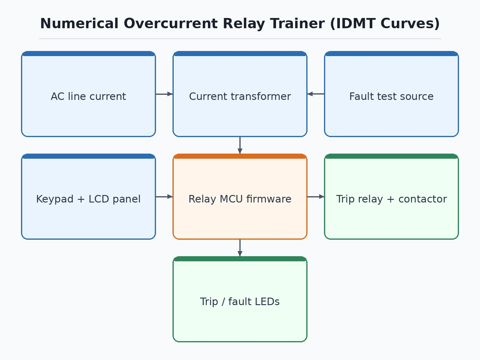
Senses load current into the burden and conditioning circuit.
Follow the working sequence
How it works
- Load current flows through the primary of the current transformer; the secondary current develops a voltage across the burden resistor.
- The conditioning circuit rectifies and scales this into the microcontroller's ADC range; firmware samples it and computes true RMS current each cycle.
- The measured current is compared with the pickup setting Is: below pickup the relay rests; above pickup the IDMT timer starts.
- The firmware evaluates the IEC 60255 curve continuously — t = TMS × k / ((I/Is)^α − 1) — with the selected curve constants (k, α) and the set TMS.
- When the computed time elapses, the trip output energizes, the contactor drops out (the "breaker" trips), LEDs flag the event, and the measured trip time is shown on the LCD.
- The student injects several fault levels with the test source, records measured versus theoretical trip times, and analyses the error — CT accuracy, sampling delay and burden effects — in the report.
Tech stack:
- Microcontroller-based numerical relay (ADC sampling, RMS computation)
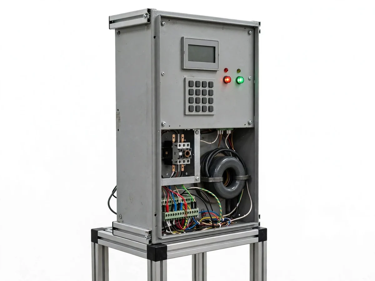
- Current transformer with burden resistor and conditioning circuit
- IEC 60255 IDMT curves: NI, VI, EI (+ definite-time, instantaneous)
- Keypad + LCD for pickup, TMS and curve selection
- Variable-current fault injection test source (~20 A design range)
- Trip contactor (breaker simulator), indication LEDs, reset circuit
| Parameter | Value |
|---|---|
| Relay type | Numerical overcurrent, microcontroller-based |
| Characteristics | NI / VI / EI per IEC 60255: t = TMS × k / ((I/Is)^α − 1) |
| Pickup setting | Adjustable Is (design range set by CT ratio) |
| TMS range | 0.1–1.0 in 0.05 steps (design target) |
| Test source | Adjustable fault current, up to ~20 A (design range) |
| Trip output | Relay contact driving contactor (breaker simulator) |
| Trip-time display | Measured pickup-to-trip time on LCD |
| Timing accuracy | Design target ±5% of theoretical curve; verified by buyer tests |
| Supply | 230 V AC single phase for panel and test source |
Project features
- [True IDMT characteristics] Normal Inverse, Very Inverse and Extremely Inverse curves implemented per the IEC 60255 formula t = TMS × k / ((I/Is)^α − 1), computed live on the microcontroller — not a lookup table.
- [Settable pickup and TMS] Pickup current (Is) and time-multiplier setting are adjustable through the keypad and LCD, so the student can reshape the curve and watch trip times change.
- [CT-based current sensing] A real current transformer with burden resistor and precision-rectifier conditioning feeds the ADC; the manual explains CT ratio, burden and why sensing accuracy limits relay accuracy.
- [Adjustable fault test source] A variable-current test source (up to ~20 A design range) injects controlled overcurrents, letting the student run repeatable trip-time tests at several multiples of pickup.
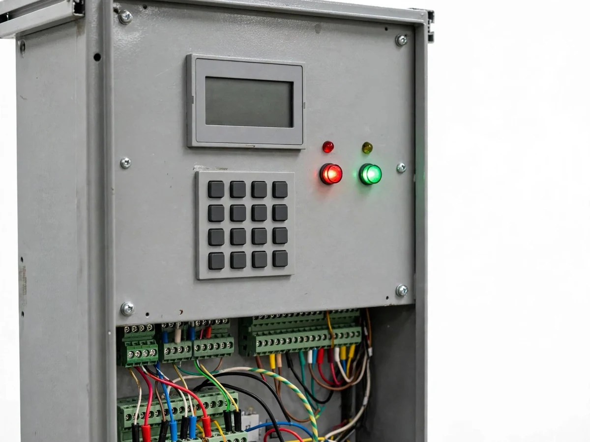
- [Trip output and breaker simulator] The relay's trip contact drives a contactor representing the circuit breaker, with trip/fault LEDs and a manual reset — the complete protection chain in miniature.
- [Trip-time measurement] The controller timestamps pickup and trip events and displays the measured operating time, ready to be plotted against the theoretical IDMT curve for the error analysis.
- [Definite-time and instantaneous elements] Alongside IDMT, a definite-time delay and an instantaneous (high-set) element are implemented, demonstrating relay coordination concepts.
What is included
- Working numerical overcurrent relay trainer panel with CT sensing, keypad/LCD, trip contactor and test source
- Experiment manual: setup, CT and burden explanation, setting procedure, trip-time test protocol, error-analysis worksheets
- Project report PDF (background, protection theory, IDMT mathematics, firmware logic, buyer-run trip-time results)
- PPT presentation for final review
- Viva Q&A preparation document (IDMT curves, TMS, CT errors, coordination, definite vs inverse time)
- Setup and safety guide (test-source current limits, insulation, never connect to real switchgear)
Advantages
- True IDMT characteristics for Normal, Very and Extremely Inverse curves are computed live from the IEC 60255 formula, not from a lookup table.
- Adjustable pickup current and time-multiplier setting let students reshape the curve through the keypad and LCD and watch trip times change.
- A real current transformer with burden resistor and precision-rectifier conditioning feeds the ADC, so the manual can teach CT ratio, burden and sensing accuracy limits.
- The adjustable fault-current test source lets students run repeatable trip-time tests at several multiples of pickup.
- Trip timestamps and a definite-time plus instantaneous element complete the protection chain, with the trip contact driving a contactor as breaker simulator.
Disadvantages
- This is an educational low-voltage trainer, not a certified protection relay, and it must never be connected to real switchgear, feeders or live distribution equipment.
- Trip-time accuracy is a design target of ±5% of the theoretical curve, and the buyer's own tests measure the real error including CT inaccuracy, burden effects and sampling delay.
- The test source is limited to about 20 A, so it demonstrates relay behaviour at moderate multiples of pickup, not at real short-circuit levels.
- Single-phase demonstration only, so three-phase protection concepts such as directional and differential protection are beyond this build's scope.
Limitations & prerequisites
- This is an educational low-voltage trainer, not a certified protection relay: it must never be connected to real switchgear, feeders or any live distribution equipment — the safety guide states this explicitly.
- Trip-time accuracy is a design target (±5% of the theoretical curve); the buyer's own tests measure the real error, which includes CT inaccuracy, burden effects and sampling delay — the report analyses it honestly.
- The test source is limited to about 20 A; it demonstrates relay behaviour at moderate multiples of pickup, not short-circuit levels of a real system.
- Single-phase demonstration only; three-phase protection concepts (directional, differential) are beyond this build's scope.
Frequently Asked Questions
Which IDMT curves are implemented?
Normal Inverse, Very Inverse and Extremely Inverse per the IEC 60255 formula t = TMS × k / ((I/Is)^α − 1), computed live — plus definite-time and instantaneous elements for coordination study.
How do I verify the relay actually follows the curve?
Inject fault currents at several multiples of pickup with the test source, read the measured trip time on the LCD, and plot measured versus theoretical — the manual's worksheets walk through the error analysis.
Can this relay protect real equipment?
No. It is an educational trainer for low-voltage bench use only and must never be wired to real switchgear or live feeders. Real protection needs certified relays with tested breaking capacity.
What does TMS actually change?
The time-multiplier setting scales the whole IDMT curve up or down in time — raising TMS delays tripping at every current level, which is how engineers coordinate upstream and downstream relays.
What are the main limitations?
Bench trainer only, never for real switchgear; timing is a design target verified by your tests; ~20 A test source; single-phase demonstration.
Is this project suitable for a final-year project?
Yes — for Electrical Engineering programs. It demonstrates protection philosophy, IDMT mathematics, CT sensing, relay coordination and honest measurement-versus-theory analysis. Suitable for B.E./B.Tech final-year projects in Electrical Engineering.
Components & software requirements
- Microcontroller-based numerical relay (ADC sampling, RMS computation)
- Current transformer with burden resistor and conditioning circuit
- IEC 60255 IDMT curves: NI, VI, EI (+ definite-time, instantaneous)
- Keypad + LCD for pickup, TMS and curve selection
- Variable-current fault injection test source (~20 A design range)
- Trip contactor (breaker simulator), indication LEDs, reset circuit
Delivery information
Built-to-order project. Delivery timeline is shared after order confirmation based on current queue.
Support terms
Complete documentation, setup guide, and viva preparation included. Support for setup and explanation provided.
Download free synopsis (PDF)
Enter your name and WhatsApp number — the synopsis PDF downloads immediately. We may send occasional project updates on WhatsApp; no spam.