
More project photos (2)
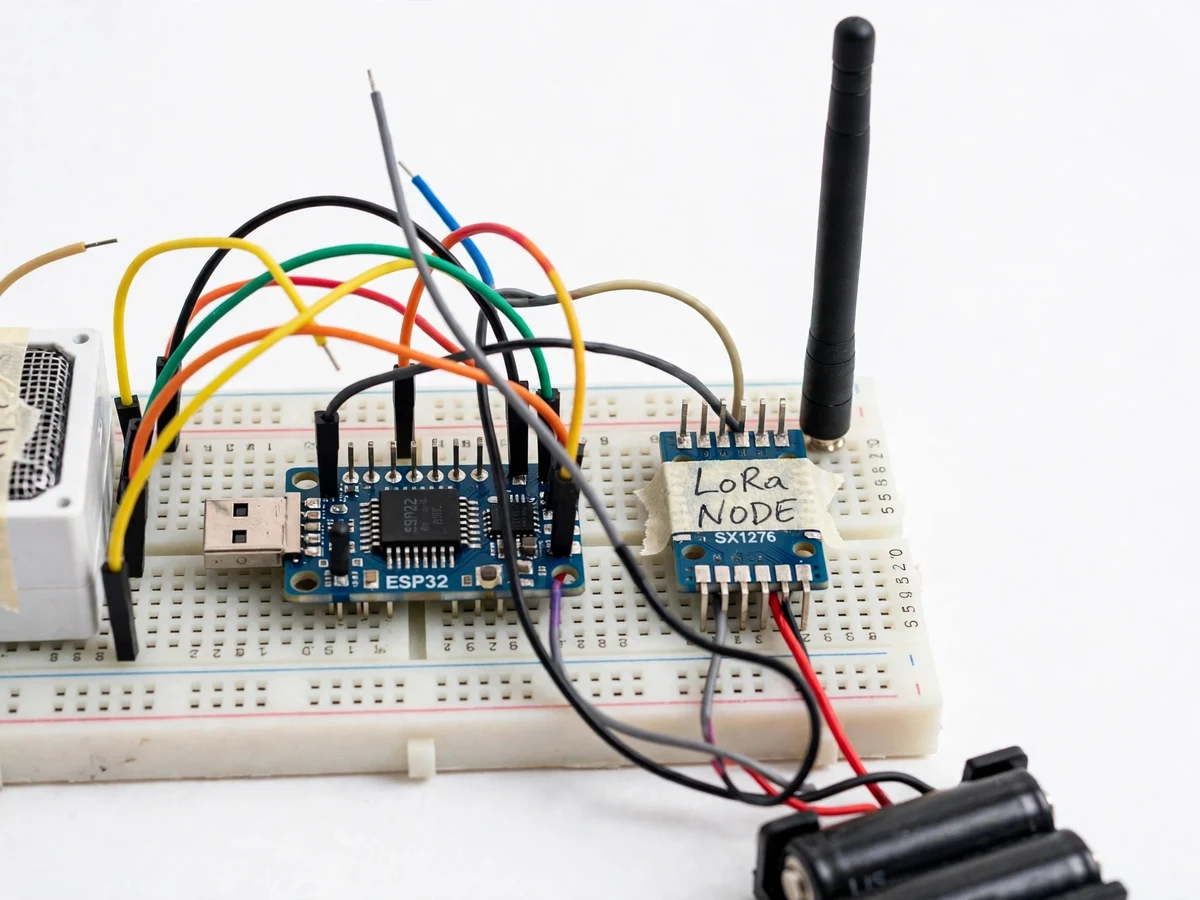
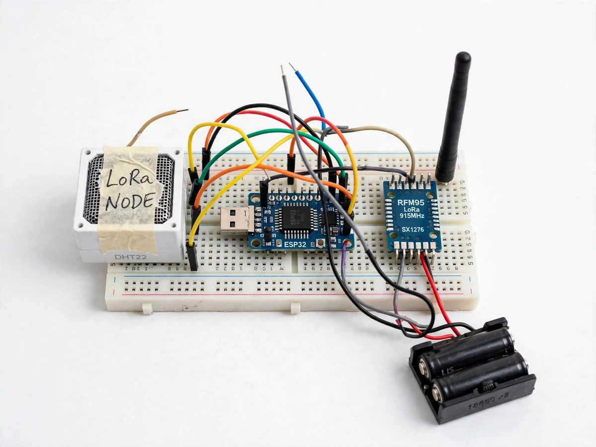
The problem
Weather monitoring in farms, campuses and industrial yards fails at the connectivity step: WiFi does not reach the field, and GSM data plans cost money every month for a few bytes of sensor data. LoRa exists precisely for this gap — a chirp spread-spectrum radio that trades bitrate for kilometres of range on milliwatts of power, in licence-free spectrum. This project builds the classic LoRa weather pair: a remote node with an ESP32, an RFM95 LoRa module and a DHT22 temperature-humidity sensor (plus a pressure sensor), and a base-station node with its own LoRa receiver and an LCD showing live readings. The demo places the sensor node across the lab or campus and streams packets to the receiver, showing live temperature, humidity, packet count and signal strength. Students learn the full wireless-sensor-network pipeline — sensing, packet framing with node IDs and checksums, link-budget thinking and the deep-sleep discipline that lets a node live on batteries.
How it works
- The sensor node wakes from deep sleep, powers the DHT22 and pressure sensor, and takes stabilized readings.
- The ESP32 packs the readings with its node ID, an incrementing sequence number and a checksum into a compact LoRa packet.
- The RFM95 transmits the packet on 865 MHz using chirp spread-spectrum modulation at the configured spreading factor.
- The receiver node's RFM95 picks up the packet; the firmware verifies the checksum and discards any corrupted frames.
- Valid readings are shown on the receiver's LCD with temperature, humidity, pressure, RSSI and sequence number.
- The sensor node returns to deep sleep until the next cycle, and the receiver logs the stream over serial for analysis.
Tech stack:
- ESP32 DevKit (sensor node and receiver node)
- RFM95 LoRa module (SX1276, 865 MHz ISM)
- DHT22 temperature-humidity sensor
- Barometric pressure sensor (BMP280)
- 16x2 LCD on receiver node
- Battery pack for sensor node
- Arduino IDE (C/C++ firmware, RadioLib/LoRa library)
- Serial monitor for packet logging
| Parameter | Value |
|---|---|
| Radio | SX1276-based RFM95, 865 MHz (India ISM), chirp spread spectrum |
| Design range target | Up to ~2 km line-of-sight in open conditions (actual range depends on terrain, antenna height and obstructions — measured by buyer during field test) |
| Sensors | DHT22: ±0.5 °C, ±2–5% RH (datasheet); BMP280 pressure ±1 hPa (datasheet) |
| Packet format | Node ID + sequence + sensor payload + checksum, verified at receiver |
| Transmit interval | Configurable, default every 5 minutes |
| Power | Sensor node: battery pack with ESP32 deep sleep between cycles; receiver: USB powered |
| Display | Receiver 16x2 LCD: live readings + RSSI + sequence |
| Link visibility | RSSI and packet counter shown per packet for link-quality analysis |
Project features
- [Long-range LoRa link] RFM95 (SX1276) modules on 865 MHz — India's licence-free ISM band — carry sensor packets point-to-point with a design target of up to ~2 km in open line-of-sight conditions.
- [Temperature, humidity and pressure sensing] The node reads a DHT22 (±0.5 °C, ±2% RH per datasheet) and a barometric pressure sensor, transmitting all three in each packet.
- [Structured packets with checksum] Every transmission carries a node ID, sequence number, sensor payload and checksum, so the receiver rejects corrupted packets instead of displaying garbage.
- [Receiver display station] The base node shows live temperature, humidity, pressure, last-packet RSSI and packet sequence on an LCD — the link health is visible at a glance.
- [Deep-sleep power design] The sensor node spends most of its life in ESP32 deep sleep, waking every few minutes to sense and transmit — the standard technique for battery-powered field nodes.
- [Configurable radio parameters] Spreading factor, bandwidth and transmit power are adjustable in firmware, letting the student demonstrate the range-vs-airtime tradeoff in the viva.
- [Battery operation] The sensor node runs from a battery pack, so the demo genuinely shows untethered field operation rather than a bench-bound prototype.
What is included
- Two working LoRa nodes: battery-powered sensor node + LCD receiver station (ESP32, RFM95 modules, DHT22, BMP280, antennas)
- Complete firmware for both nodes (packet framing, checksum, deep sleep, receiver display)
- Radio configuration guide (frequency, spreading factor, bandwidth, power settings for India)
- Field-test procedure (range walk-test with RSSI logging template)
- Circuit and wiring documentation
- Project report PDF (LoRa modulation background, link budget, packet design, power analysis)
- PPT presentation for final review
- Viva Q&A preparation document (spread spectrum, ISM bands, deep sleep, checksums)
- Setup and demonstration guide
Limitations & prerequisites
- The ~2 km figure is a design target for open line-of-sight; buildings, trees and terrain reduce real range significantly — the field-test procedure exists precisely to measure this honestly.
- LoRa is low-bitrate by design (tens of bytes per packet, minutes between transmissions); it cannot carry video, audio or web traffic.
- Operation is on the 865–867 MHz ISM band with duty-cycle discipline; the firmware defaults respect this, and continuous transmission is not permitted.
- The receiver shows data on its LCD and serial log only — there is no cloud dashboard or phone app in this build; that is a separate project.
- Weatherproofing the field node (enclosure, sensor radiation shield) is documented as a buyer-done step; the kit ships as an electronics prototype.
Frequently Asked Questions
What is LoRa and why use it here?
LoRa is a chirp spread-spectrum radio modulation that trades data rate for exceptional range and low power in licence-free sub-GHz spectrum. Weather telemetry is the textbook use case: a few bytes of temperature and humidity every few minutes, from locations WiFi cannot reach, with no SIM card or data plan. The project demonstrates the full wireless sensor node pattern — sense, frame, transmit, sleep.
What frequency does it use in India?
The RFM95 modules are configured for 865 MHz, inside India's 865–867 MHz licence-free ISM band. Spreading factor, bandwidth, coding rate and transmit power are all firmware-adjustable, so you can demonstrate the range-versus-airtime tradeoff live in the viva. The configuration guide documents legal, duty-cycle-respecting defaults for the demo.
How far will it actually reach?
The design target is up to about 2 km in open line-of-sight conditions, but real range depends heavily on terrain, antenna height, buildings and vegetation. Rather than claim a number, the kit includes a walk-test procedure: carry the node outward while the receiver logs RSSI and packet sequence, producing an honest measured range plot for your report.
Does it need internet or a SIM card?
No. The sensor node and receiver communicate directly, radio to radio, with no gateway, router or cellular network involved. That is the point of the architecture — it works in fields and remote sites with zero infrastructure. The tradeoff is that data only exists at the receiver's LCD and serial log; there is no cloud dashboard in this build.
What sensors are on the node?
A DHT22 measures temperature (±0.5 °C) and humidity (±2–5% RH), and a BMP280 adds barometric pressure (±1 hPa) — all manufacturer datasheet specifications. The firmware reads each sensor, packs the values with a node ID, sequence number and checksum into one compact packet, and transmits on the configured interval.
Is this project suitable for a final-year project?
Yes — for IoT, Electronics and Communication programs. Spread-spectrum radio, packet framing with checksums, link-budget reasoning and deep-sleep power management are all current, viva-rich topics, and the live across-campus demo is memorable. The field-test procedure also teaches honest experimental characterization. Suitable for B.E./B.Tech final-year projects in IoT, Electronics and Communication engineering.
Components & software requirements
- ESP32 DevKit (sensor node and receiver node)
- RFM95 LoRa module (SX1276, 865 MHz ISM)
- DHT22 temperature-humidity sensor
- Barometric pressure sensor (BMP280)
- 16x2 LCD on receiver node
- Battery pack for sensor node
- Arduino IDE (C/C++ firmware, RadioLib/LoRa library)
- Serial monitor for packet logging
Delivery information
Built-to-order project. Delivery timeline is shared after order confirmation based on current queue.
Support terms
Complete documentation, setup guide, and viva preparation included. Support for setup and explanation provided.