
More project photos (2)
The problem
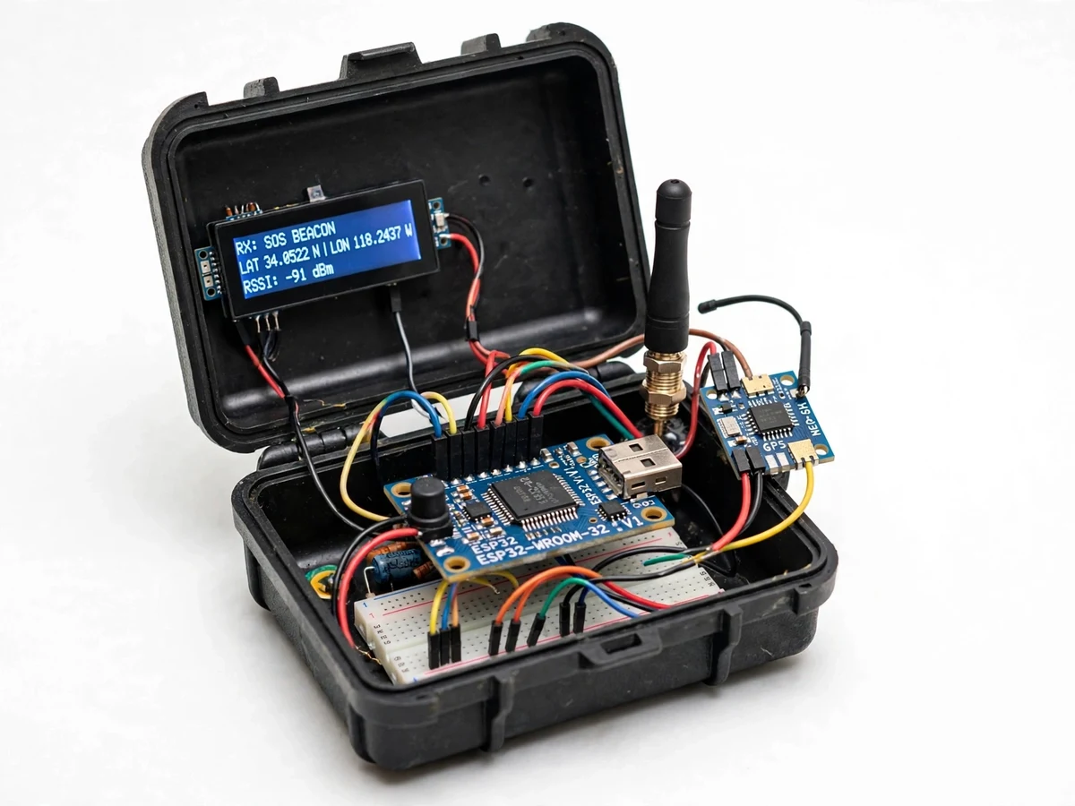
Hikers, trekkers and field workers routinely go where phones show no signal, and that is exactly where an emergency is hardest to report. Commercial satellite messengers solve this but cost far more than a student budget allows. LoRa offers a middle path: license-free long-range radio that can carry a short GPS position packet several kilometers to a base station at the trailhead or camp. This project builds that system as two units — a pocket SOS beacon (ESP32, GPS, LoRa, panic button, battery) and a base-station receiver (ESP32, LoRa, display, buzzer). One press sends the coordinates; the base station alerts and displays them with a map link. It is a genuine long-range embedded-wireless build and an honest one: range depends on terrain, and it is a prototype, not a certified rescue device.
How it works
- The hiker presses the panic button; the ESP32 wakes from deep sleep and powers the GPS receiver.
- The NEO-6M acquires a satellite fix (needs open sky) and the firmware parses latitude and longitude from the NMEA sentences.
- The beacon builds a short packet — device ID, coordinates, battery level, SOS flag — and transmits it over LoRa at 433 MHz.
- The base-station ESP32, listening continuously, receives and validates the packet's ID and checksum.
- The base station sounds its buzzer and displays the coordinates, signal strength and a ready-to-open map link on the OLED.
- The base station transmits an acknowledgement packet; on receipt, the beacon lights its confirmation LED so the hiker knows help was alerted.
Tech stack:
- ESP32 development modules (beacon and base station)
- SX1276-based LoRa modules (433 MHz ISM band)
- NEO-6M GPS receiver with antenna
- 18650 Li-ion cell with charger module (beacon power)
- OLED display and buzzer (base-station alerts)
- Tactile panic button with debounce logic
- Arduino IDE firmware (deep sleep, NMEA parsing, packet protocol)
- Compact handheld enclosure for the beacon
| Parameter | Value |
|---|---|
| Radio | LoRa, SX1276-based module, 433 MHz ISM band |
| Range | Design target: several km line-of-sight (terrain and antenna dependent; not guaranteed) |
| Position | NEO-6M GPS; cold-start fix time per the module datasheet (open sky required) |
| Packet | Device ID, latitude, longitude, battery level, SOS/check-in flag, checksum |
| Beacon power | 18650 Li-ion cell; deep-sleep standby estimated at multiple days (usage dependent) |
| Base station | ESP32 + LoRa + OLED + buzzer, USB powered |
| Check-in interval | Configurable in firmware (SOS is always immediate) |
| Acknowledgement | Base-to-beacon ACK packet with LED confirmation |
| Enclosure | Compact handheld prototype case (beacon); desktop case (base) |
| Demo scope | Two-unit link demonstration; not a certified rescue device |
Project features
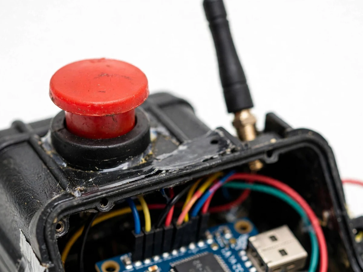
- One-press SOS transmission: A large tactile panic button with debouncing and a deliberate press pattern wakes the beacon and fires the SOS packet.
- Live GPS coordinates: A NEO-6M GPS receiver acquires the position fix; the packet carries latitude, longitude, battery level and a device ID.
- Long-range LoRa link: An SX1276-based 433 MHz LoRa module with configurable spreading factor trades data rate for range on the license-free ISM band.
- Base-station receiver: A second ESP32 with LoRa validates incoming packets, sounds a buzzer, and shows coordinates, received signal strength and a map link on its OLED.
- Acknowledgement downlink: The base station replies with an ACK packet; the beacon's LED confirms to the hiker that the SOS was received.
- Low-power trek design: The beacon sleeps in deep sleep between scheduled check-ins, waking on button press or timer, for multi-day battery standby (estimated).
- Scheduled check-in mode: Optional periodic position pings at a configurable interval, so the base station can track progress even without an SOS.
- Rugged prototype enclosure: A compact handheld case for the beacon with the button, LED and charging port accessible.
What is included
- Assembled SOS beacon unit (ESP32, GPS, LoRa, battery, panic button, enclosure)
- Assembled base-station receiver (ESP32, LoRa, OLED, buzzer)
- ESP32 firmware source code for both units (GPS parsing, LoRa protocol, sleep modes)
- Wiring diagrams and antenna notes
- Component list with module details
- Project report PDF (background, LoRa theory, link budget notes, protocol design, field test procedure)
- PPT presentation for final review
- Viva Q&A preparation document (LoRa modulation, spreading factor, GPS NMEA, power budgeting, ISM regulations)
- Field-test and safe-use guide
Limitations & prerequisites
- Range is environment-dependent: the design target of several kilometers assumes line-of-sight; hills, forest and buildings reduce it substantially, and no range figure is guaranteed.
- GPS needs open sky: fixes fail indoors, in deep valleys and under dense canopy, and cold-start acquisition takes time per the module datasheet.
- This is an academic prototype, not a certified personal locator beacon: it must never be relied upon as a sole means of rescue, and the report states this explicitly.
- The 433 MHz ISM band is license-free in many regions but regulations and permitted power vary by country — the user must check local rules.
- Battery standby estimates depend on check-in interval, temperature and cell condition; cold weather shortens runtime markedly.
- The system needs its paired base station within radio range to be useful — unlike satellite messengers it cannot reach the outside world on its own.
Frequently Asked Questions
Which modules are used?
An ESP32 plus a NEO-6M GPS receiver and an SX1276-based LoRa module (433 MHz) in the beacon; a second ESP32 with LoRa, OLED and buzzer forms the base station.
How far does it really reach?
The design target is several kilometers with line-of-sight. Terrain dominates real range — hills and forest cut it sharply — so the report documents a field-test procedure rather than claiming a fixed number.
Does it need the internet or cellular?
No. Beacon-to-base communication is direct LoRa radio; the base station works fully offline. The map link is just coordinates formatted for any map app.
How long does the battery last?
The beacon sleeps in deep sleep between check-ins; standby is estimated at multiple days depending on the check-in interval, temperature and cell condition.
Can more beacons join one base station?
Yes — each packet carries a device ID, so the base station firmware can track multiple beacons; multi-beacon support is a documented customization.
What will I receive?
Both assembled units, firmware source for beacon and base, wiring diagrams, report PDF, PPT, viva Q&A and the field-test guide. Suitable for B.E./B.Tech final-year projects in Electronics, IoT and Embedded Systems.
Components & software requirements
- ESP32 development modules (beacon and base station)
- SX1276-based LoRa modules (433 MHz ISM band)
- NEO-6M GPS receiver with antenna
- 18650 Li-ion cell with charger module (beacon power)
- OLED display and buzzer (base-station alerts)
- Tactile panic button with debounce logic
- Arduino IDE firmware (deep sleep, NMEA parsing, packet protocol)
- Compact handheld enclosure for the beacon
Delivery information
Built-to-order project. Delivery timeline is shared after order confirmation based on current queue.
Support terms
Complete documentation, setup guide, and viva preparation included. Support for setup and explanation provided.