
More project photos (2)
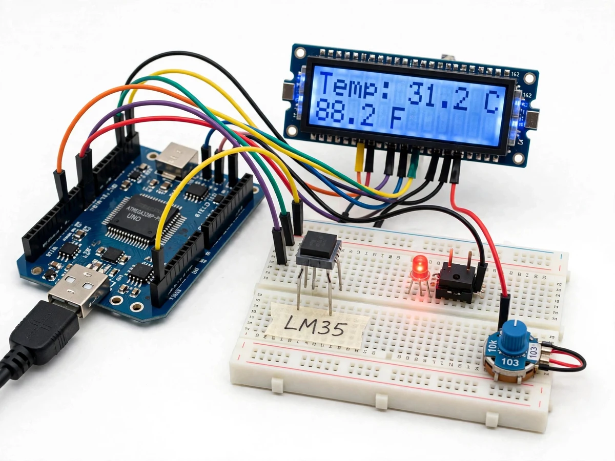
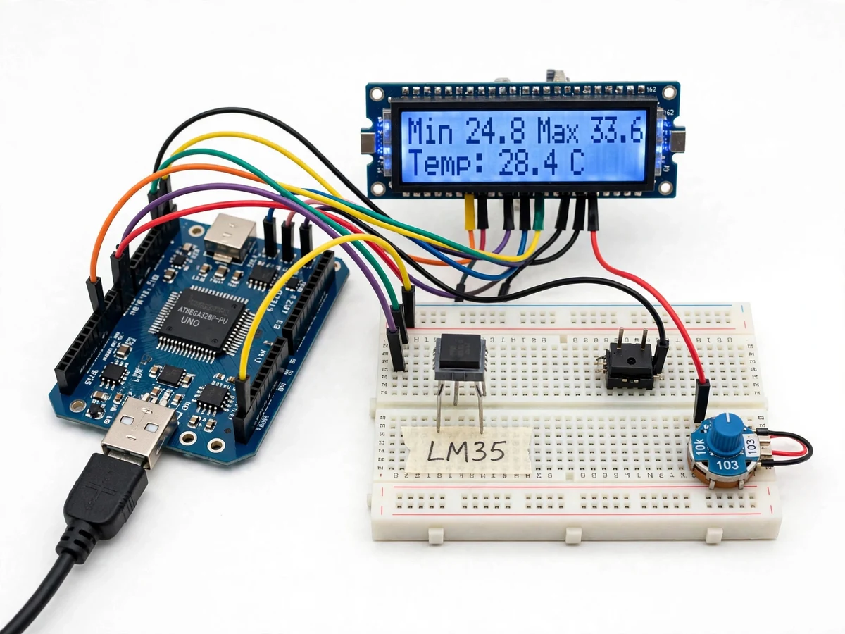
The problem
Most students measure temperature with a glass thermometer or a handheld meter, which gives one reading, no record of peaks, and no warning at a limit. The LM35 Digital Thermometer with Arduino and LCD solves this by turning temperature into a voltage the Arduino can read continuously: the LM35 sensor outputs 10 mV for every degree Celsius, the Arduino Uno digitises that voltage with its 10-bit ADC, and the result appears on a 16×2 LCD in both °C and °F. A buzzer sounds when the temperature crosses a set limit, and the firmware remembers the lowest and highest readings since switch-on, so a student can see the full range of an experiment without watching the display. Because the sensor needs no calibration, draws under 60 µA, and connects with three wires, the build stays simple for a first embedded project while teaching analog sensing, ADC conversion, unit conversion, and threshold logic in one working instrument.
Outputs 10 mV for every degree Celsius.
Follow the working sequence
How it works
Temperature becomes a number on the LCD through a short chain that starts at the sensor and ends at the display. The LM35 produces an analog voltage of 10 mV for every degree Celsius, so 25 °C appears as 250 mV at the sensor output pin. The Arduino Uno reads that voltage on an analog pin with its 10-bit ADC, which divides the 0–5 V range into 1,024 steps of about 4.88 mV, and converts the count back into degrees Celsius by dividing by 10, then into Fahrenheit with the standard formula. Firmware averages several samples to smooth noise, updates the LCD about once a second, compares the result with the alarm limit, and refreshes the stored minimum and maximum. The whole loop repeats continuously, so the display always shows the current temperature.
- The LM35 is wired to 5 V, ground and Arduino analog pin A0, with a 100 nF capacitor across the sensor supply pins close to the sensor to steady the reading.
- The Arduino ADC samples the sensor output 10 times in quick succession and averages the samples to reduce noise.
- The averaged ADC count is converted to voltage, then to Celsius by dividing the millivolt value by 10, and to Fahrenheit using °F = °C × 9/5 + 32.
- The LCD shows the live temperature in °C and °F, and a push-button toggles the display to the stored minimum and maximum readings.
- The firmware compares the temperature with the alarm limit on every cycle; above the limit it switches on the buzzer and red LED until the temperature falls back.
- The minimum and maximum values are updated on every cycle, and the reset button clears them for a fresh measurement run.
Tech stack:
- Arduino Uno (ATmega328P)
- LM35 temperature sensor
- 16×2 LCD with I2C adapter
- Arduino IDE
- Embedded C · C++
- Active buzzer module
- Breadboard prototyping
- 5 V USB power supply
| Parameter | Value |
|---|---|
| Sensor | LM35 analog temperature sensor (TI datasheet) |
| Sensor output | 10 mV per °C (datasheet) |
| Sensor accuracy | ±0.5 °C at 25 °C (datasheet, ensured) |
| Sensor range | −55 °C to +150 °C (datasheet); single-supply circuit reads from approximately +2 °C |
| ADC resolution | 10-bit, approximately 4.88 mV per step (derived) |
| Display | 16×2 character LCD showing °C and °F |
| Display update | Approximately 1 second (design target) |
| Alarm threshold | Configurable, default 40 °C |
| Alarm output | Active buzzer + red LED |
| Min/max memory | Stored in RAM, clears on power-off |
| Supply | 5 V via USB, approximately 100 mA (expected) |
| Demonstration range | Approximately 2 °C to 100 °C (design target) |
Project features
The thermometer is built around four capabilities that make it more than a bare sensor demo. First, it measures and displays temperature continuously in both Celsius and Fahrenheit on a 16×2 LCD, so the reading is always visible without a computer. Second, it watches a configurable high-temperature limit and sounds a buzzer with a red LED the moment the limit is crossed, turning a passive meter into an alarm. Third, it tracks the minimum and maximum temperatures since switch-on, giving the student a simple record of the experiment's extremes. Fourth, it steadies its own readings by averaging multiple ADC samples and by decoupling the sensor supply, a small piece of real engineering that keeps the last digit from flickering. Together these make a complete, demonstrable instrument rather than a wiring exercise.
- [Dual-unit LCD display] The 16×2 LCD shows the live temperature in °C on the first line and °F on the second, updated about once a second, so the reading is readable from across a bench without a laptop.
- [High-temperature buzzer alarm] When the temperature crosses the set limit (default 40 °C), an active buzzer sounds and a red LED lights, and both stay on until the temperature falls back below the limit.
- [Min/max temperature memory] The firmware continuously tracks the lowest and highest temperatures since switch-on, and a push-button switches the LCD to a min/max screen so the extremes of an experiment are always available.
- [Averaged ADC sampling] Each displayed reading is the average of 10 consecutive ADC samples, which smooths electrical noise and stops the last digit flickering on the display.
- [Simple three-wire sensor] The LM35 connects with only power, ground and one analog output wire, needs no calibration, and draws under 60 µA, so the sensor stage is easy to wire, explain and debug.
- [Configurable alarm limit] The high-temperature threshold is a single named constant in the firmware, so it can be changed for a different experiment without touching the rest of the code.
- [One-button reset] A push-button clears the stored min/max values, so each new experiment starts from a clean record without re-uploading the firmware.
What is included
- Working prototype (Arduino Uno, LM35 sensor, 16×2 LCD, buzzer, breadboard wiring)
- Complete Arduino firmware with comments (sampling, averaging, display, alarm, min/max)
- Circuit and wiring diagram with component list
- Buyer-run verification procedure (room-temperature check, warm-water check, alarm-limit check)
- Project report PDF (background, LM35 theory, methodology, results procedure)
- PPT presentation for final review
- Viva Q&A preparation document (analog sensing, ADC conversion, sensor datasheet values)
Limitations & prerequisites
- The single-supply circuit cannot read below approximately +2 °C; negative temperatures need the dual-supply circuit from the LM35 datasheet.
- Displayed resolution is about 0.5 °C per ADC step, so the last digit is a guide, not a precision measurement.
- Accuracy is bounded by the sensor's ±0.5 °C at 25 °C (datasheet) plus ADC quantization; no laboratory-grade accuracy is claimed.
- The sensor must touch the surface or medium being measured; air-temperature readings lag behind fast changes.
- Long sensor leads pick up electrical noise, so leads are kept short in the build and the averaging step is part of the design.
- Min/max values live in RAM only and are lost when the board is powered off.
- This is an academic prototype, not a certified or medical thermometer.
Frequently Asked Questions
What does the LM35 sensor actually output?
The LM35 outputs an analog voltage of 10 mV for every degree Celsius, so 25 °C gives 250 mV and 40 °C gives 400 mV, and the Arduino reads this voltage with its 10-bit ADC. That linear relationship is the whole measurement principle: the firmware divides the millivolt reading by 10 to get Celsius, then applies the standard formula for Fahrenheit. No lookup table or calibration curve is needed because the sensor is factory-calibrated in degrees Celsius.
How accurate is the thermometer?
The LM35 is rated at ±0.5 °C accuracy at 25 °C in the TI datasheet, and the Arduino's 10-bit ADC adds roughly one quantization step of about 0.5 °C. In practice the display is reliable to about ±1 °C for room-temperature and bench experiments, which suits a teaching prototype. It is not a calibrated laboratory instrument, and the report states the datasheet limits honestly instead of claiming a tighter figure.
Can the high-temperature alarm limit be changed?
Yes, the alarm limit is a single named constant in the firmware with a default of 40 °C, so changing it means editing one line and re-uploading the sketch. The buzzer and red LED then trigger above the new limit and switch off once the temperature falls back below it. This makes the same build usable for different experiments, such as monitoring a motor housing or a water bath.
What will I receive with the project?
You receive the working prototype, the commented Arduino firmware, the circuit and wiring diagram with a component list, and a buyer-run verification procedure for room temperature, warm water and the alarm limit. The documentation set includes the project report PDF, a PPT for the final review, and a viva Q&A document covering analog sensing, ADC conversion and the LM35 datasheet values.
Is this project suitable for a final-year project?
Yes, for Electronics & Telecommunication and Electrical Engineering students, because it demonstrates analog sensing, ADC conversion, embedded C firmware, LCD interfacing and threshold-based alarm logic in one working instrument. The build is compact enough to complete and explain confidently, while the datasheet study, averaging method and verification procedure give the report real technical depth for the viva.
Components & software requirements
- Arduino Uno (ATmega328P)
- LM35 temperature sensor
- 16×2 LCD with I2C adapter
- Arduino IDE
- Embedded C · C++
- Active buzzer module
- Breadboard prototyping
- 5 V USB power supply
Delivery information
Built-to-order project. Delivery timeline is shared after order confirmation based on current queue.
Support terms
Complete documentation, setup guide, and viva preparation included. Support for setup and explanation provided.
Download free synopsis (PDF)
Enter your name and WhatsApp number — the synopsis PDF downloads immediately. We may send occasional project updates on WhatsApp; no spam.